|
|
|
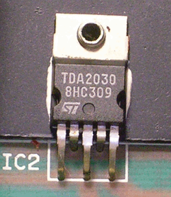
PDF TDA2030 Data sheet ( Hoja de datos )
| Número de pieza | TDA2030 | |
| Descripción | 14W HI-FI AUDIO AMPLIFIER | |
| Fabricantes | Unisonic Technologies | |
| Logotipo | ||
 1. Hi-Fi Audio Amplifier - ST Hay una vista previa y un enlace de descarga de TDA2030 (archivo pdf) en la parte inferior de esta página. Total 13 Páginas | ||
|
No Preview Available !
UNISONIC TECHNOLOGIES CO., LTD
TDA2030
LINEAR INTEGRATED CIRCUIT
14W HI-FI AUDIO AMPLIFIER
DESCRIPTION
The UTC TDA2030 is a monolithic audio power amplifier
integrated circuit.
FEATURES
* Very low external component required.
* High current output and high operating voltage.
* Low harmonic and crossover distortion.
* Built-in Over temperature protection.
* Short circuit protection between all pins.
* Safety Operating Area for output transistors.
ORDERING INFORMATION
Ordering Number
Normal
Lead Free Plating
TDA2030-TA5-T
TDA2030L-TA5-T
TDA2030-TB5-T
TDA2030L-TB5-T
Package
TO-220-5
TO-220B
*Pb-free plating product number: TDA2030L
Packing
Tube
Tube
PIN CONFIGURATION
PIN NO.
1
2
3
4
5
PIN NAME
Non inverting input
Inverting input
-VS
Output
+VS
www.unisonic.com.tw
Copyright © 2007 Unisonic Technologies Co., Ltd
1 of 13
QW-R107-004,D
1 page 
TDA2030
LINEAR INTEGRATED CIRCUIT
+Vs
C1
Vi2.2 F
R1
56k
1
R3
56k
R2 2
56k
R6
1.5
5
UTC
TDA2030
3
C5
220 F
/40V
4
R4
3.3k
C4
10 F
R5
30k
R7
1.5
C8
2200 F
R8
1
C7
0.22 F
Fig. 1 Single supply high power amplifier
TYPICAL PERFORMANCE OF THE CIRCUIT OF FIG. 1
PARAMETER
Supply Voltage
Quiescent Drain Current
Output Power
Voltage Gain
Slew Rate
Total Harmonic Distortion
Input Sensitivity
Signal to Noise Ratio
SYMBOL
Vs
IQ
POUT
Gv
SR
d
VIN
S/N
TEST CONDITIONS
Vs=36V
d=0.5%,RL=4Ω
f=40Hz to 15kHz,Vs=39V
d=0.5%,RL=4Ω
f=40Hz to 15kHz,Vs=36V
d=10%,f=1kHz,
RL=4Ω,Vs=39V
d=10%,RL=4Ω
f=1kHz,Vs=36V
f=1kHz
POUT=20W,f=1kHz
POUT=20W,f=40Hz to 15kHz
Gv=20dB,POUT=20W,
f=1kHz,RL=4Ω
RL=4Ω,Rg=10kΩ
B=curve A,POUT=25W
RL=4Ω,Rg=10kΩ
B=curve A,POUT=4W
MIN
19.5
TYP MAX UNIT
36 44
V
50 mA
35
28
W
44
35
20 20.5 dB
8 V/µsec
0.02 %
0.05 %
890 mV
108 dB
100
UNISONIC TECHNOLOGIES CO., LTD
www.unisonic.com.tw
5 of 13
QW-R107-004,D
5 Page 
TDA2030
LINEAR INTEGRATED CIRCUIT
The result is an AC signal at the output whole peak-to-peak value is the TIM voltage, which can be measured
easily with an oscilloscope. If the peak-topeak value of the signal and the peak-to-peak of the inverting sawtooth are
measured, the TIM can be found very simply from:
VOUT
TIM =
* 100
Vsawtooth
In Fig.8 The experimental results are shown for the 30W amplifier using the UTC TDA2030 as a driver and a
low-cost complementary pair. A simple RC filter on the input of the amplifier to limit the maximum signal slope(SS) is
an effective way to reduce TIM.
The Diagram of Fig.9 can be used to find the Slew-Rate(SR) required for a given output power or voltage and a
TIM design target.
For example if an anti-TIM filter with a cutoff at 30kHz is used and the max. peak to peak output voltage is 20V
then, referring to the diagram, a Slew-Rate of 6V/µs is necessary for 0.1% TIM.
As shown Slew-Rates of above 10V/µs do not contribute to a further reduction in TIM.
Slew-Rates of 100V/µs are not only useless but also a disadvantage in hi-fi audio amplifiers because they tend to
turn the amplifier into a radio receiver.
UNISONIC TECHNOLOGIES CO., LTD
www.unisonic.com.tw
11 of 13
QW-R107-004,D
11 Page | ||

| Páginas | Total 13 Páginas | |
| PDF Descargar | [ Datasheet TDA2030.PDF ] | |
Hoja de datos destacado
| Número de pieza | Descripción | Fabricantes |
| TDA2030 | 14W HI-FI AUDIO AMPLIFIER | Unisonic Technologies |
| TDA2030 | 14W Hi-Fi AUDIO AMPLIFIER | ST Microelectronics |
| TDA2030 | 18W Hi-Fi AMPLIFIER AND 35W DRIVER | WISWOOD |
| TDA2030A | 18W Hi-Fi AMPLIFIER AND 35W DRIVER | ST Microelectronics |
| Número de pieza | Descripción | Fabricantes |
| SLA6805M | High Voltage 3 phase Motor Driver IC. |
Sanken |
| SDC1742 | 12- and 14-Bit Hybrid Synchro / Resolver-to-Digital Converters. |
Analog Devices |
|
DataSheet.es es una pagina web que funciona como un repositorio de manuales o hoja de datos de muchos de los productos más populares, |
| DataSheet.es | 2020 | Privacy Policy | Contacto | Buscar |