|
|
|
PDF UM0984 Data sheet ( Hoja de datos )
| Número de pieza | UM0984 | |
| Descripción | STEVAL-ISA081V1 demonstration board based on a 12V / 1A isolated flyback User manual | |
| Fabricantes | STMicroelectronics | |
| Logotipo | ||
Hay una vista previa y un enlace de descarga de UM0984 (archivo pdf) en la parte inferior de esta página. Total 25 Páginas | ||
|
No Preview Available !
UM0984
User manual
STEVAL-ISA081V1 demonstration board based on a 12 V / 1 A
isolated flyback
Introduction
The purpose of this document is to provide information on the STEVAL-ISA081V1 switched
mode power supply (SMPS) demonstration board. The STEVAL-ISA081V1 is an isolated
SMPS capable of delivering a 12 W output over a wide input voltage range. It is designed for
a mains application focused on providing a cost-effective and space saving solution.
The STEVAL-ISA081V1 SMPS generates 12 V nominal output voltage using primary
regulation. This board is based on VIPer™26LD - a monolithic converter integrating a high
voltage MOSFET and PWM controller in one package.
This document contains a fundamental technical description of the demonstration board
(schematic diagram, PCB details, and bill of materials) as well as basic measurements
(load regulation, efficiency, standby behavior, EMI and thermal behavior data).
The last section of this document contains short recommendations on how to set different
output voltages in the range of 10 to 18 V and how to improve efficiency up to 86%.
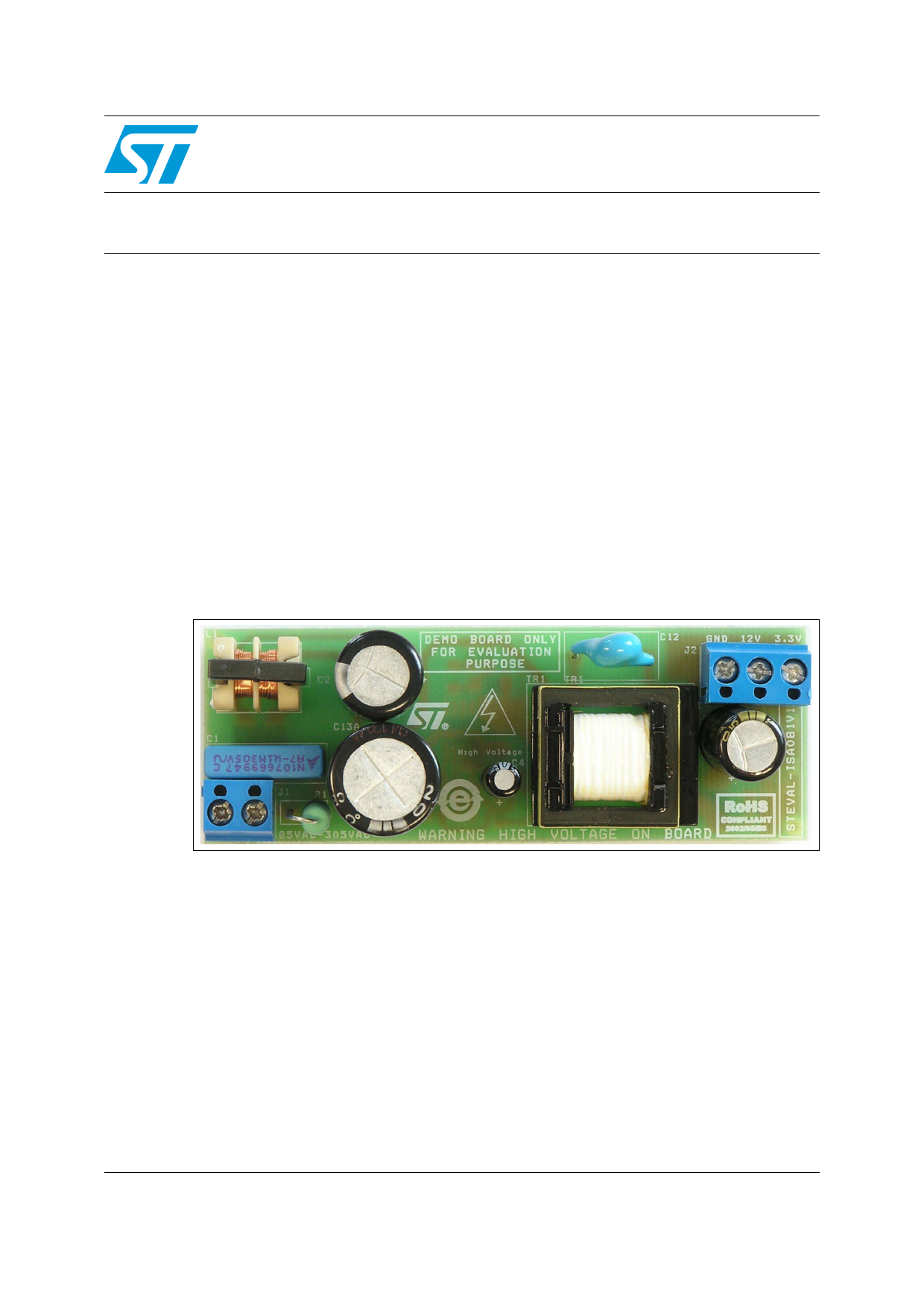
Figure 1. Demonstration board STEVAL-ISA081V1
June 2012
Doc ID 17812 Rev 2
1/25
www.st.com
http://www.Datasheet4U.com
1 page 
UM0984
1 Mai
n characteristics
The main characteristics of the SMPS are listed below
● Input:
–V IN: 85 ~ 305 V rms
– frequency: 45 ~ 66 Hz
● Output:
– 12 VDC ± 10%, 1 A (at 3.3 V not loaded)
– 3.3 VDC ± 4%, 100 mA
– Maximum total output current of 1 A
● Standby < 120 mW at 230 VAC
● Short-circuit: protected
● PCB type and size:
–F R4
– Single-sided 35 µm
– 32 x 90 mm
● Isolation: isolated 4 kV / 8 mm
● EMI: according to EN55022 Class B
Main characteristics
Doc ID 17812 Rev 2
5/25
5 Page 
UM0984
Figure 4. Transformer construction
Board description
3.4 L
ayout
The layout of the PCB is based on a single-sided FR4, with 35 µm thickness. The size of the
PCB is 32 x 90 mm. The distance between the primary and secondary side is higher than
8 mm, respecting the safety requirements for all standard applications. The layout of the
PCB is provided in Figure 5.
The layout was designed with respect to the following rules to achieve stable operation,
good efficiency and reduce EMI noise.
● The power HF tracks are wide and short:
– Transformer to IC1
– Transformer to C13
– IC1 to C13
– Transformer to C8
– C8 to D3
– Transformer to D3
– Peak clamp loop
● The power and signal GND of VIPER26LD are separated and connected only in one
point close to the source pins
● The EMI filter has been placed far from the transformer to avoid possible crosstalk of
EMI noise
Doc ID 17812 Rev 2
11/25
11 Page | ||
| Páginas | Total 25 Páginas | |
| PDF Descargar | [ Datasheet UM0984.PDF ] | |
Hoja de datos destacado
| Número de pieza | Descripción | Fabricantes |
| UM0984 | STEVAL-ISA081V1 demonstration board based on a 12V / 1A isolated flyback User manual | STMicroelectronics |
| Número de pieza | Descripción | Fabricantes |
| SLA6805M | High Voltage 3 phase Motor Driver IC. |
Sanken |
| SDC1742 | 12- and 14-Bit Hybrid Synchro / Resolver-to-Digital Converters. |
Analog Devices |
|
DataSheet.es es una pagina web que funciona como un repositorio de manuales o hoja de datos de muchos de los productos más populares, |
| DataSheet.es | 2020 | Privacy Policy | Contacto | Buscar |