|
|
|
PDF ISL21009MEP Data sheet ( Hoja de datos )
| Número de pieza | ISL21009MEP | |
| Descripción | High Voltage Input Precision Low Noise FGA Voltage References | |
| Fabricantes | Intersil Corporation | |
| Logotipo | ||
Hay una vista previa y un enlace de descarga de ISL21009MEP (archivo pdf) en la parte inferior de esta página. Total 14 Páginas | ||
|
No Preview Available !
®
Data Sheet
December 15, 2008
ISL21009MEP
www.DataSheet4U.com
FN6744.0
High Voltage Input Precision, Low Noise
FGA™ Voltage References
The ISL21009MEP FGA™ voltage references are extremely
low power, high precision, and low noise voltage references
fabricated on Intersil’s proprietary Floating Gate Analog
technology. The ISL21009MEP features very low noise
(4.5µVP-P for 0.1Hz to 10Hz), low operating current (180µA,
Max), and 3ppm/°C of temperature drift. In addition, the
ISL21009 family features guaranteed initial accuracy as low
as ±0.5mV.
This combination of high initial accuracy, low power and low
output noise performance of the ISL21009MEP enables
versatile high performance control and data acquisition
applications with low power consumption.
Device Information
The specifications for an Enhanced Product (EP) device are
defined in a Vendor Item Drawing (VID), which is controlled
by the Defense Supply Center in Columbus (DSCC).
“Hot-links” to the applicable VID and other supporting
application information are provided on our website.
Available Options
PART NUMBER
ISL21009BMB825EP
ISL21009CMB825EP
ISL21009BMB841EP
ISL21009BMB850EP
ISL21009CMB850EP
VOUT
OPTION
(V)
2.500
2.500
4.096
5.000
5.000
INITIAL
ACCURACY
(mV)
±0.5
±1.0
±0.5
±0.5
±1.0
TEMPCO.
(ppm/°C)
3
5
3
3
5
Features
• Specifications per DSCC VID V62/08629
• Full Mil-Temp Electrical Performance from -55°C to +125°C
• Controlled Baseline with One Wafer Fabrication Site and
One Assembly/Test Site
• Full Homogeneous Lot Processing in Wafer Fab
• No Combination of Wafer Fabrication Lots in Assembly
• Full Traceability Through Assembly and Test by
Date/Trace Code Assignment
• Enhanced Process Change Notification
• Enhanced Obsolescence Management
• Eliminates Need for Up-Screening a COTS Component
• Output Voltages . . . . . . . . . . . . . . 2.500V, 4.096V, 5.000V
• Initial Accuracy . . . . . . . . . . . . . . . . . . . . .±0.5mV, ±1.0mV
• Input Voltage Range. . . . . . . . . . . . . . . . . . . 3.5V to 16.5V
• Output Voltage Noise . . . . . . . . .4.5µVP-P (0.1Hz to 10Hz)
• Supply Current . . . . . . . . . . . . . . . . . . . . . . . .180µA (Max)
• Temperature Coefficient . . . . . . . . . . . . 3ppm/°C, 5ppm/°C
• Output Current Capability. . . . . . . . . . . . . . . Up to ±7.0mA
• Operating Temperature Range. . . . . . . . . -55°C to +125°C
• Package . . . . . . . . . . . . . . . . . . . . . . . . . . . . . . 8 Ld SOIC
Applications
• Defense/Commercial Avionics
• Radar/Sonar Systems
• Signal Processing Applications
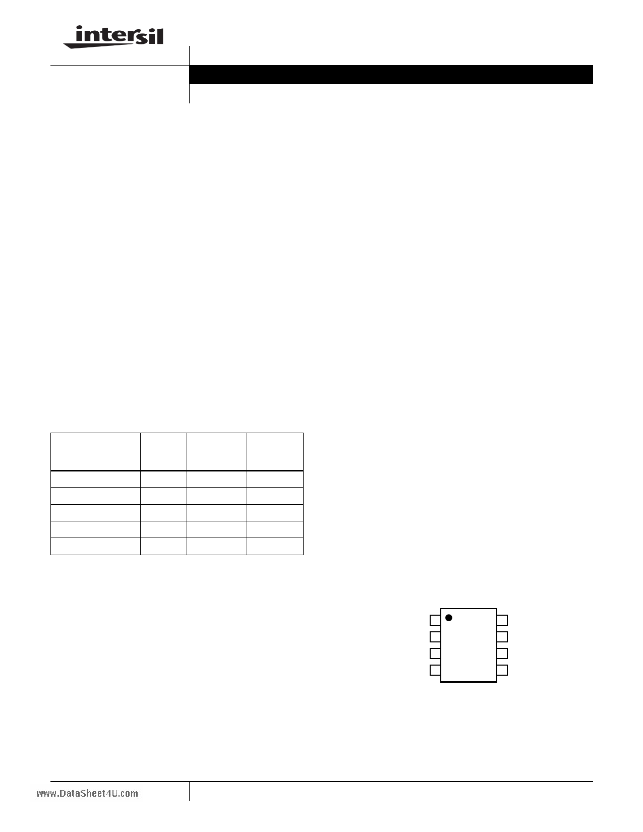
Pinout
ISL21009MEP
(8 LD SOIC)
TOP VIEW
GND or NC 1
VIN 2
DNC 3
GND 4
8 DNC
7 DNC
6 VOUT
5 TRIM or NC
1 CAUTION: These devices are sensitive to electrostatic discharge; follow proper IC Handling Procedures.
1-888-INTERSIL or 1-888-468-3774 | Intersil (and design) is a registered trademark of Intersil Americas Inc.
FGA is a trademark of Intersil Corporation. Copyright Intersil Americas Inc. 2008. All Rights Reserved
All other trademarks mentioned are the property of their respective owners.
1 page 
ISL21009MEP
Typical Performance Curves (ISL21009-25EP) (REXT = 100kΩ) (Continued)
www.DataSheet4U.com
NO OUTPUT CAPACITANCE
+50µA
NO OUTPUT CAPACITANCE
7mA
-50µA
-7mA
FIGURE 14. LOAD TRANSIENT RESPONSE
FIGURE 15. LOAD TRANSIENT RESPONSE
Typical Performance Curves (ISL21009-41EP) (REXT = 100kΩ)
110 100
105
100
UNIT 3
95
UNIT 2
90
UNIT 1
85
95 +25°C
90
+125°C
85
-40°C
80
5 7 9 11 13 15
VIN (V)
FIGURE 16. IIN vs VIN, 3 UNITS
17
80
5 7 9 11 13 15
VIN (V)
FIGURE 17. IIN vs VIN, 3 TEMPERATURES
17
4.0963
4.0962
4.0962
4.0961
4.0961
4.0960
4.0960
4.0959
4.0959
4.0958
4.50
UNIT 1
UNIT 3
UNIT 2
6.50
8.50 10.5
12.5
14.5
VIN (V)
FIGURE 18. LINE REGULATION, 3 UNITS
16.5
200
150
100 +25°C
50 -55°C
0
-50 +125°C
-100
4.5
6.5
8.5
10.5
12.5
14.5
16.5
VIN (V)
FIGURE 19. LINE REGULATION OVER-TEMPERATURE
5 FN6744.0
December 15, 2008
5 Page 
ISL21009MEP
Board Mounting Considerations
For applications requiring the highest accuracy, board
mounting location should be reviewed. The device uses a
plastic SOIC package, which will subject the die to mild
stresses when the PC board is heated and cooled, slightly
changing the shape. Placing the device in areas subject to
slight twisting can cause degradation of the accuracy of the
reference voltage due to these die stresses. It is normally
best to place the device near the edge of a board, or the
shortest side, as the axis of bending is most limited at that
location. Mounting the device in a cutout also minimizes flex.
Obviously mounting the device on flexprint or extremely thin
PC material will likewise cause loss of reference accuracy.
Noise Performance and Reduction
The output noise voltage in a 0.1Hz to 10Hz bandwidth is
typically 4.5µVP-P. The noise measurement is made with a
bandpass filter made of a 1-pole high-pass filter with a corner
frequency at 0.1Hz and a 2-pole low-pass filter with a corner
frequency at 12.6Hz to create a filter with a 9.9Hz bandwidth.
Noise in the 10kHz to 1MHz bandwidth is approximately
40µVP-P with no capacitance on the output. This noise
measurement is made with a 2 decade bandpass filter made
of a 1-pole high-pass filter with a corner frequency at 1/10 of
the center frequency and 1-pole low-pass filter with a corner
frequency at 10x the center frequency. Load capacitance up
to 1000pF can be added but will result in only marginal
improvements in output noise and transient response. The
output stage of the ISL21009MEP is not designed to drive
heavily capactive loads, so for load capacitances above
0.001µF, the noise reduction network shown in Figure 44 is
recommended. This network reduces noise significantly over
the full bandwidth. Noise is reduced to less than 20µVP-P from
1Hz to 1MHz using this network with a 0.01µF capacitor and a
2kΩ resistor in series with a 10µF capacitor. Also, transient
response is improved with higher value output capacitor. The
0.01µF value can be increased for better load transient
response with little sacrifice in output stability.
.
VIN = 5.0V
0.1µF
10µF
VIN
VO
ISL21009-25EP
GND
0.01µF
2kΩ
10µF
Turn-On Time
www.DataSheet4U.com
The ISL21009MEP devices have low supply current and
thus the time to bias up internal circuitry to final values will
be longer than with higher power references. Normal turn-on
time is typically 100µs. This is shown in Figure 11. Circuit
design must take this into account when looking at power-up
delays or sequencing.
Temperature Coefficient
The limits stated for temperature coefficient (tempco) are
governed by the method of measurement. The overwhelming
standard for specifying the temperature drift of a reference is to
measure the reference voltage at two temperatures, take the
total variation, (VHIGH – VLOW), and divide by the temperature
extremes of measurement (THIGH – TLOW). The result is
divided by the nominal reference voltage (at T = +25°C) and
multiplied by 106 to yield ppm/°C. This is the “Box” method for
specifying temperature coefficient.
Output Voltage Adjustment
The output voltage can be adjusted up or down by 2.5% by
placing a potentiometer from VOUT to GND and connecting the
wiper to the TRIM pin. The TRIM input is high impedance so no
series resistance is needed. The resistor in the potentiometer
should be a low tempco (<50ppm/°C) and the resulting voltage
divider should have very low tempco <5ppm/°C. A digital
potentiometer such as the ISL95810 provides a low tempco
resistance and excellent resistor and tempco matching for trim
applications.
FIGURE 44. HANDLING HIGH LOAD CAPACITANCE
11 FN6744.0
December 15, 2008
11 Page | ||
| Páginas | Total 14 Páginas | |
| PDF Descargar | [ Datasheet ISL21009MEP.PDF ] | |
Hoja de datos destacado
| Número de pieza | Descripción | Fabricantes |
| ISL21009MEP | High Voltage Input Precision Low Noise FGA Voltage References | Intersil Corporation |
| Número de pieza | Descripción | Fabricantes |
| SLA6805M | High Voltage 3 phase Motor Driver IC. |
Sanken |
| SDC1742 | 12- and 14-Bit Hybrid Synchro / Resolver-to-Digital Converters. |
Analog Devices |
|
DataSheet.es es una pagina web que funciona como un repositorio de manuales o hoja de datos de muchos de los productos más populares, |
| DataSheet.es | 2020 | Privacy Policy | Contacto | Buscar |