|
|
|
PDF ISL12058 Data sheet ( Hoja de datos )
| Número de pieza | ISL12058 | |
| Descripción | Low Cost and Low Power I2C-Bus Real Time Clock/Calendar | |
| Fabricantes | Intersil Corporation | |
| Logotipo | ||
Hay una vista previa y un enlace de descarga de ISL12058 (archivo pdf) en la parte inferior de esta página. Total 19 Páginas | ||
|
No Preview Available !
www.DataSheet4U.com
ISL12058
®
Low Cost and Low Power I2C-Bus™ Real Time Clock/Calendar
Data Sheet
June 15, 2009
FN6756.0
Low Power and Low Cost RTC with Alarm
Function
The ISL12058 device is a low power real time clock with
clock/calendar, and alarm function.
The oscillator uses an external, low-cost 32.768kHz crystal.
The real time clock tracks time with separate registers for
hours, minutes, and seconds. The device has calendar
registers for date, month, year and day of the week. The
calendar is accurate through 2099, with automatic leap year
correction.
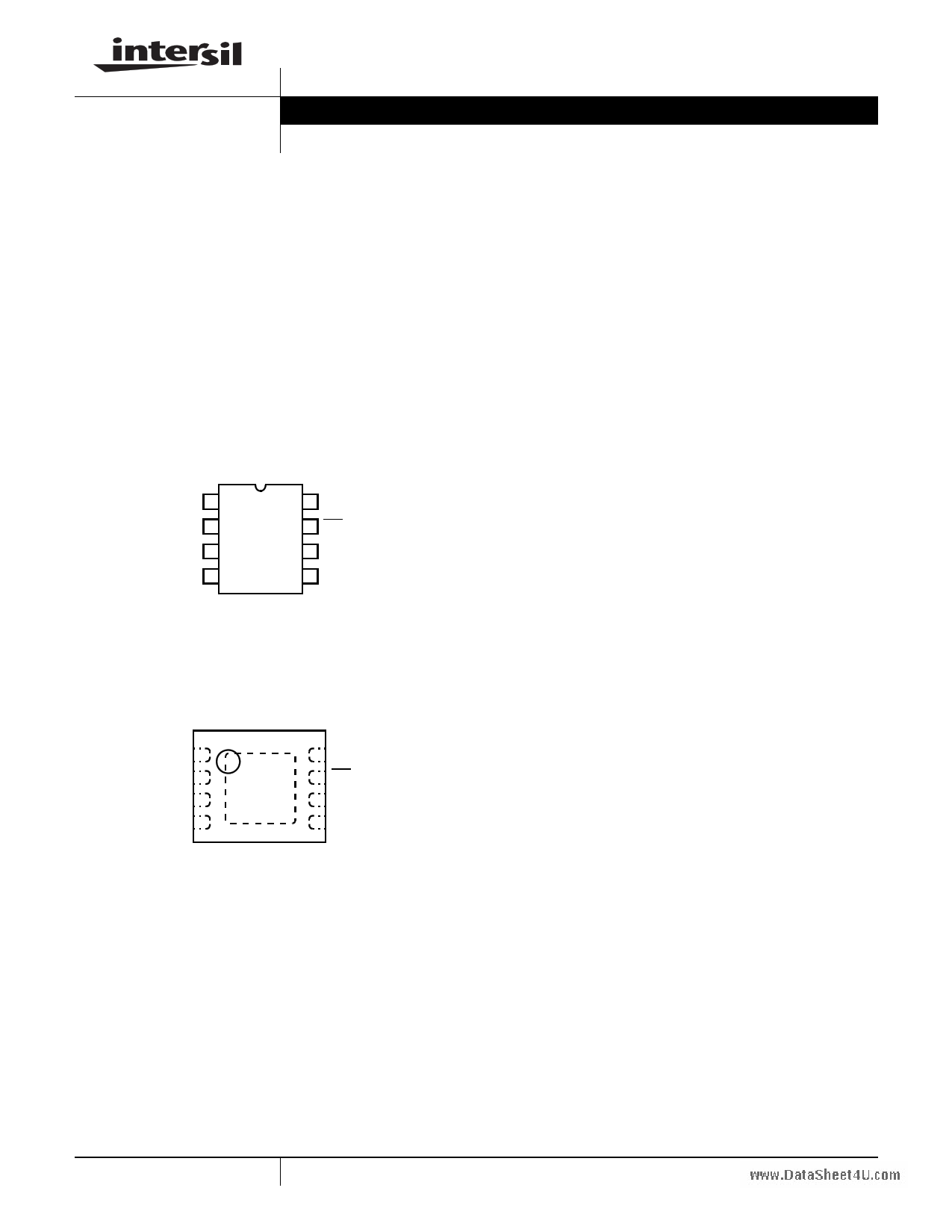
Pinouts
ISL12058
(8 LD SOIC, MSOP)
TOP VIEW
X1 1
X2 2
NC 3
GND 4
8 VDD
7 IRQ/FOUT
6 SCL
5 SDA
ISL12058
(8 LD 2x2 µTDFN, 8 LD 3x3 TDFN)
TOP VIEW
X1 1
X2 2
NC 3
GND 4
8 VDD
7 IRQ/FOUT
6 SCL
5 SDA
Features
• Real Time Clock/Calendar
- Tracks Time in Hours, Minutes, and Seconds
- Day of the Week, Date, Month, and Year
• 4 Selectable Frequency Outputs
• 2 Alarms
- Settable to the Second, Minute, Hour, Day of the Week,
Date, or Month
• I2C Interface
- 400kHz Data Transfer Rate
• Small Package Options
- 8 Ld 2mmx2mm µTDFN Package
- 8 Ld 3mmx3mm TDFN Package
- 8 Ld MSOP Package
- 8 Ld SOIC Package
- Pb-Free (RoHS Compliant)
• Low Cost 3V Alternative to ISL1208 and ISL12082
Applications
• Utility Meters
• HVAC Equipment
• Audio/Video Components
• Set-Top Box/Television
• Modems
• Network Routers, Hubs, Switches, Bridges
• Cellular Infrastructure Equipment
• Fixed Broadband Wireless Equipment
• Pagers/PDA
• Point Of Sale Equipment
• Test Meters/Fixtures
• Office Automation (Copiers, Fax)
• Home Appliances
• Computer Products
• Other Industrial/Medical/Automotive
1 CAUTION: These devices are sensitive to electrostatic discharge; follow proper IC Handling Procedures.
1-888-INTERSIL or 1-888-468-3774 | Intersil (and design) is a registered trademark of Intersil Americas Inc.
Copyright Intersil Americas Inc. 2009. All Rights Reserved
I2C-bus™ All other trademarks mentioned are the property of their respective owners.
1 page 
ISL12058
www.SDaetraiSahleIent4teUr.cfaomce Specifications Over the recommended operating conditions unless otherwise specified. (Continued)
SYMBOL
PARAMETER
TEST CONDITIONS
MIN MAX
(Note 8) TYP (Note 7) (Note 8) UNITS NOTES
tIN Pulse width Suppression Time at Any pulse narrower than the max
SDA and SCL Inputs
spec is suppressed
50 ns
tAA
tBUF
SCL Falling Edge to SDA Output
Data Valid
SCL falling edge crossing 30% of
VDD, until SDA exits the 30% to
70% of VDD window
Time the Bus Must be Free Before
the Start of a New Transmission
SDA crossing 70% of VDD during a
STOP condition, to SDA crossing
70% of VDD during the following
START condition
1300
900 ns 11
ns
tLOW Clock LOW Time
Measured at the 30% of VDD
crossing
1300
ns
tHIGH Clock HIGH Time
Measured at the 70% of VDD
crossing
600
ns
tSU:STA
tHD:STA
tSU:DAT
tHD:DAT
tSU:STO
tHD:STO
tDH
tR
tF
Cb
START Condition Setup Time
SCL rising edge to SDA falling
edge. Both crossing 70% of VDD
600
START Condition Hold Time
From SDA falling edge crossing
30% of VDD to SCL falling edge
crossing 70% of VDD
600
Input Data Setup Time
From SDA exiting the 30% to 70%
of VDD window, to SCL rising edge
crossing 30% of VDD
100
Input Data Hold Time
From SCL falling edge crossing
30% of VDD to SDA entering the
30% to 70% of VDD window
0
STOP Condition Setup Time
From SCL rising edge crossing
70% of VDD, to SDA rising edge
crossing 30% of VDD
600
STOP Condition Hold Time
From SDA rising edge to SCL
falling edge. Both crossing 70% of
VDD
600
Output Data Hold Time
From SCL falling edge crossing
30% of VDD, until SDA enters the
30% to 70% of VDD window
0
SDA and SCL Rise Time
From 30% to 70% of VDD
20 + 0.1 x Cb
SDA and SCL Fall Time
From 70% to 30% of VDD
20 + 0.1 x Cb
Capacitive Loading of SDA or SCL Total on-chip and off-chip
10
ns
ns
ns
900 ns
ns
ns
ns
300 ns 9, 10
300 ns 9, 10, 11
400 pF 9, 10
Rpu SDA and SCL Bus Pull-Up
Resistor Off-Chip
Maximum is determined by tR and
tF.
For Cb = 400pF, max is about
2kΩ to~2.5kΩ.
For Cb = 40pF, max is about 15kΩ
to ~20kΩ
1
kΩ 9, 10
NOTES:
6. IRQ/FOUT inactive.
7. Typical values are for T = +25°C and 3.3V supply voltage.
8. Parameters with MIN and/or MAX limits are 100% tested at +25°C, unless otherwise specified. Temperature limits established by
characterization and are not production tested.
9. Limits should be considered typical and are not production tested.
10. These are I2C specific parameters and are not production tested, however, they are used to set conditions for testing devices to
validate specification.
11. Parts will work with SDA pull-up voltage above the VPULLUP limit but the tAA and tFin the I2C parameters are not guaranteed.
12. Specified at +25°C.
5 FN6756.0
June 15, 2009
5 Page 
ISL12058
www.DatTaASBhLeEet44U. .FcUomNCTION SELECTION OF IRQ/FOUT PIN WITH
A1E AND IRQE BITS (Continued)
A1E IRQE
10
11
IRQ/FOUT FUNCTION
FOUT
Alarm 1 Interrupt
FREQUENCY OUT CONTROL BITS (FO <1:0>)
These bits select the output frequency at the IRQ/FOUT pin.
IRQE must be set to “0” for frequency output at the
IRQ/FOUT pin. Refer to Table 5 for frequency selection.
TABLE 5. FREQUENCY SELECTION OF IRQ/FOUT PIN WITH
FO1 AND FO0 BITS
FO1
FO0
FREQUENCY,
FOUT (Hz)
COMMENT
11
32768
Free running crystal clock
10
8192
Free running crystal clock
01
4096
Free running crystal clock
00
1
Sync. at RTC write
ALARM ENABLE BITS (ALM1E, ALM2E)
This bit enables/disables the Alarm1 and Alarm2 function.
When the ALM1E bit is set to “1”, the Alarm1 function is
enabled. When the ALM1E is cleared to “0”, the alarm function
is disabled. ALM1E bit is set to “0” at power-up.
When the ALM2E bit is set to “1”, the Alarm2 function is
enabled. When the ALM2E is cleared to “0”, the alarm function
is disabled. ALM2E bit is set to “0” at power-up.
NOTE: The Alarm1 has hardware function via the IRQ/FOUT pin.
Alarm2 does not have hardware interrupt function.
Alarm1 Registers
Addresses [Address 0Ch to 11h]
The Alarm1 register bytes are set up identical to the RTC
register bytes, except that the MSB of each byte functions as
an enable bit (enable = “1”). These enable bits specify which
alarm registers (seconds, minutes, etc) are used to make the
comparison. Note that there is no alarm byte for year. When
all the enable bits are set to “0” with ALM1E set to “1”, the
Alarm 1 will triggered once a second.
The Alarm1 function works as a comparison between the
Alarm1 registers and the RTC registers. As the RTC
advances, the Alarm1 will be triggered once a match occurs
between the Alarm1 registers and the RTC registers. Any
one Alarm1 register, multiple registers, or all registers can be
enabled for a match.
To clear an Alarm1, the A1F status bit can be set to “0” with a
write or use the ARST bit auto reset function.
TABLE 6. ALARM1 INTERRUPT WITH ENABLE BITS SELECTION
A1M1 A1M2 A1M3 A1M4 A1M5 A1M6
ALARM1
Interrupt
0 0 0 0 0 0 Every Second
1 0 0 0 0 0 Match Second
0 1 0 0 0 0 Match Minute
0 0 1 0 0 0 Match Hour
0 0 0 1 0 0 Match Date
0 0 0 0 1 0 Match Month
00
00
01
Match Day
1 1 0 0 0 0 Match Second
and Minute
1 0 1 0 0 0 Match Second
and Hour
1 1 1 0 0 0 Match Second,
Minute, and Hour
......
......
......
0 0 0 1 1 1 Match Date,
Month, and Day
1 0 0 1 1 1 Match Second,
Date, Month, and
Day
......
......
. ....
.
.
.
0 1 1 1 1 1 Match MInute,
Hour, Date,
Month, and Day
1 1 1 1 1 1 Match Second,
MInute, Hour,
Date, Month, and
Day
Following is example of Alarm1 Interrupt.
Example – A single alarm will occur on January 1 at
11:30am.
A. Set Alarm1 registers as follows:
11 FN6756.0
June 15, 2009
11 Page | ||
| Páginas | Total 19 Páginas | |
| PDF Descargar | [ Datasheet ISL12058.PDF ] | |
Hoja de datos destacado
| Número de pieza | Descripción | Fabricantes |
| ISL12057 | Low Cost and Low Power I2C RTC Real Time Clock/Calendar | Intersil Corporation |
| ISL12058 | Low Cost and Low Power I2C-Bus Real Time Clock/Calendar | Intersil Corporation |
| ISL12059 | Low Cost and Low Power I2C Bus Real Time Clock/Calendar | Intersil Corporation |
| Número de pieza | Descripción | Fabricantes |
| SLA6805M | High Voltage 3 phase Motor Driver IC. |
Sanken |
| SDC1742 | 12- and 14-Bit Hybrid Synchro / Resolver-to-Digital Converters. |
Analog Devices |
|
DataSheet.es es una pagina web que funciona como un repositorio de manuales o hoja de datos de muchos de los productos más populares, |
| DataSheet.es | 2020 | Privacy Policy | Contacto | Buscar |