|
|
|
PDF UP550 Data sheet ( Hoja de datos )
| Número de pieza | UP550 | |
| Descripción | Program Controller | |
| Fabricantes | Yokogawa | |
| Logotipo | ||
Hay una vista previa y un enlace de descarga de UP550 (archivo pdf) en la parte inferior de esta página. Total 16 Páginas | ||
|
No Preview Available !
<<Contents>> <<Index>>
General
www.DataSShpeete4Uc.coimfications
GS 05E01C02-01E
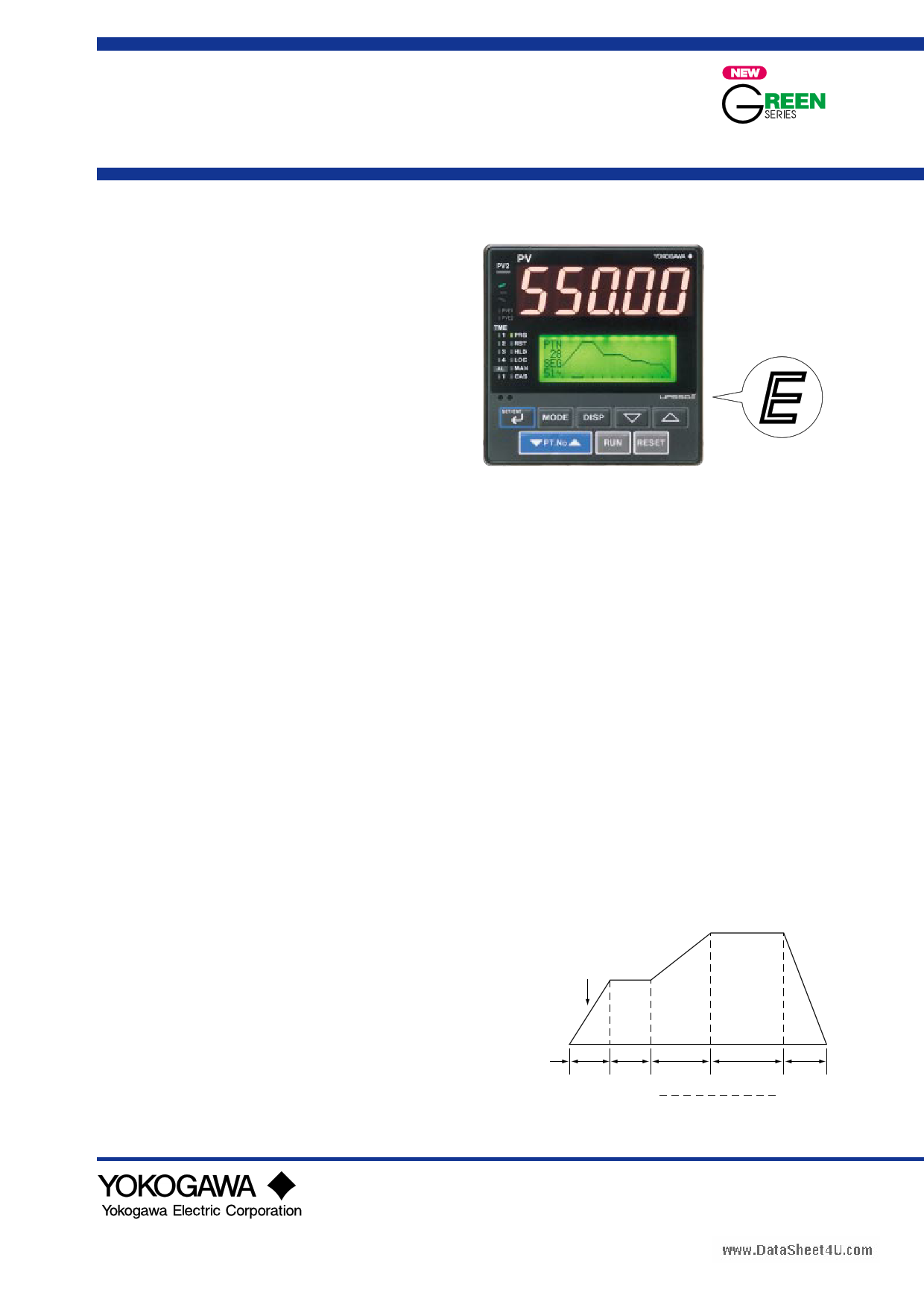
Model UP550
Program Controller
s General
Model UP550 Program Controller can store up to 30
program patterns, and has a powerful control capability and
the user-friendly large numerical display. The UP550 features
as standard many functions which are necessary for various
control applications, and all of these functions such as
program setting function, control function, control computa-
tion function, signal computation function, etc. can be
configured by using the keys on the front panel. The
instrument has five types of control strategies, and also an
overshoot suppressing function "SUPER" and a heating
suppressing function "SUPER 2" built in as standard, as
well as an auto-tuning function.
s Main Features
• Extra-large digital display allows the indicated values to be
read even from a long distance. LEDs of 20 mm height are
used for the process variable display.
This is a five-digit display for heigher resolution.
• User-friendly, full-dot LCD display, capable of showing
not only control setpoints (SPs) and parameters but also
program patterns and deviation (DV) trend logs.
• Program setting function with storage capacity for up to 30
program patterns and 300 program segments, allowing the
controller to be used for a wide range of heat-treatment
applications.
• Five types of control function, including single-loop
control, cascade control, loop control with PV auto-
selector, enabling the operator to start control operation
immediately after simply entering the settings.
• The program pattern-2 retransmission function outputs a
program pattern by way of the retransmission output. This
function is used in combination with retransmission output
setup parameter RET 1 or RET 2, for which program
pattern-2 should selected, and is used for pattern
transmission to another instrument(available for UP made
1, 2, 6 or 7).
• Parameters and program patterns can be easily set using a
personal computer. ("Parameter setting tool (model
LL100)" sold separately is required.)
• Universal input and output enables users to set or change
freely the type of measured inputs, measurement input
range, type of control output, etc. from the front panel.
• Contact inputs (up to 7 points) and contact outputs (up to 7
points) can be employed and functions can be assigned to
each contact (the maximum number of points varies
depending on the specification code), with one additional
contact input available by specifying the appropriate suffix
code. (Contact outputs can be increased up to eight; see
"Number of Event/Alarm Outputs" on page 2 or "Contact
Outputs" on page 7.)
• Various communication function are provided. Communi-
cation is possible with personal computer, programable
logic controller, and other controllers.
UP550
UP550E
“E” indicates with the
model with expanded
functions.
s Functional Specifications
q Program Setting Function
The program setting function increases or decreases the value
of a target setpoint (SP) according to a given program pattern
that varies with time. The controller stores two or more
program patterns and the operator can switch between them
according to the operating status. Each program pattern
consists of multiple line segments (program segments). The
operator sets the time interval of each program segment using
the segment time or slope. The operator can also set such
instructions as the number of repeats, start/stop, and status
output (event output) for a given program pattern.
Number of program patterns: 30 maximum
Number of program segments per pattern: 99 maximum
Number of program segments: 300 maximum (sum of
segments for all program patterns)
Configurable number of events: 400 maximum (sum of
events for all program patterns)
Number of program repeats:
999 maximum, or unlimited repeats.
Segment time: 0 minute 0 s to 59 minute 59 s, or 0 h 0
minute to 99 h 59 minute.
Start/stop of program pattern:
Program patterns can be started (RUN),
stopped (RESET), paused (hold) or advanced
by means of contact inputs or from instrument
operation.
Switching between program patterns:
Achieved by contact inputs or from instrument
operation.
Target setpoint (SP)
Segment time
t1 t2
t3
t4
Segment Segment
No. 1 No. 2
Example of Program Pattern
t5
Segment
No. 5
GS 05E01C02-01E
© Copyright Feb. 2000 (YK)
2nd Edition Jul. 2004 (YK)
1 page 
<<Contents>> <<Index>>
www.DataSheet4U.com
Examples of Communication System Configuration Diagram
(1) Personal computer link communication/
MODBUS communication
Personal computer
(2) Ladder communication
MELSEC-A
Programmable
controller
PV
PV2
AL
1
2
3 REM
4 MAN1
MAN2
STP
CAS
A/M
SET/ENT DISP
PV
PV2
AL
1
2
3 REM
4 MAN1
MAN2
STP
CAS
A/M
SET/ENT DISP
PV
PV2
AL
1
2
3 REM
4 MAN1
MAN2
STP
CAS
A/M
SET/ENT DISP
UP550
program controller
PV
PV2
AL
1
2
3 REM
4 MAN1
MAN2
STP
CAS
A/M
SET/ENT DISP
PV
PV2
AL
1
2
3 REM
4 MAN1
MAN2
STP
CAS
A/M
SET/ENT DISP
PV
PV2
AL
1
2
3 REM
4 MAN1
MAN2
STP
CAS
A/M
SET/ENT DISP
PV
PV2
AL
1
2
3 REM
4 MAN1
MAN2
STP
CAS
A/M
SET/ENT DISP
UP550
program controller
PV
PV2
AL
1
2
3 REM
4 MAN1
MAN2
STP
CAS
A/M
SET/ENT DISP
5
(3) Coordinated operation
UP550 (or UP750) program controller
PV
PV2
AL
1
2
3 REM
4 MAN1
MAN2
STP
CAS
A/M
SET/ENT DISP
PV
PV2
AL
1
2
3 REM
4 MAN1
MAN2
STP
CAS
A/M
SET/ENT DISP
PV
PV2
AL
1
2
3 REM
4 MAN1
MAN2
STP
CAS
A/M
SET/ENT DISP
PV
PV2
AL
1
2
3 REM
4 MAN1
MAN2
STP
CAS
A/M
SET/ENT DISP
PV
PV2
AL
1
2
3 REM
4 MAN1
MAN2
STP
CAS
A/M
SET/ENT DISP
UT750, UT550, UT520, UT350 or
UT320 digital indicating controller
Input type
Unspecified (When shipped from the factory)
Thermocouple K
RTD
J
T
B
S
R
N
E
L (DIN)
U (DIN)
W
Platinel 2
PR20-40
W97Re3-W75Re25
JPt100
Pt100
Standard
signal
DC voltage
0.4 to 2V
1 to 5V
0 to 2V
0 to 10V
-10 to 20mV
0 to100mV
Input range
code
Instrument
range (°C)
Instrument
range (°F)
Instrument accuracy*1
OFF Set the data item PV input type “IN 1” to the OFF option to leave the PV input type undefined.
typeK1
typeK2
typeK3
typeJ
typeT1
(1)
(2)
(3)
(4)
(5)
-270.0 to 1370.0°C
-270.0 to 1000.0°C
-200.0 to 500.0°C
-200.0 to 1200.0°C
-270.0 to 400.0°C
-450.0 to 2500.0°F
-450.0 to 2300.0°F
-200.0 to 1000.0°F
-300.0 to 2300.0°F
-450.0 to 750.0°F
±0.1% ±1 digit of instrument range at 0°C or more
±0.2% ±1 digit of instrument range at less than 0°C
• However, ±2% ±1 digit of instrument range for type K
at temperatures less than -200°C.
• However, ±1% ± 1 digit of instrument range for type T
at temperatures less than -200°C.
typeT2 (6)
0.0 to 400.0°C -200.0 to 750.0°F
typeB
(7)
0.0 to 1800.0°C
32 to 3300°F
±0.15% ±1 digit of instrument range at 400°C or more
±5% ±1 digit of instrument range at less than 400°C
typeS
(8)
0.0 to 1700.0°C
32 to 3100°F ±0.15% ± 1 digit of instrument range
typeR
(9)
0.0 to 1700.0°C
32 to 3100°F
typeN
(10) -200.0 to 1300.0°C -300.0 to 2400.0°F ±0.1% ± 1 digit of instrument range
±0.25% ±1 digit of instrument range for
temperature at less than 0°C
typeE
typeL
(11) -270.0 to 1000.0°C -450.0 to 1800.0°F ±0.1% ±1 digit of instrument range at 0°C or more
(12)
-200.0 to 900.0°C
-300.0 to 1600.0°F
±0.2% ±1 digit of instrument range at less than 0°C
• However, ±1.5% ±1 digit of instrument range for
typeU1 (13) -200.0 to 400.0°C -300.0 to 750.0°F
type E at temperature less than -200°C.
typeU2 (14)
0.0 to 400.0°C -200.0 to 1000.0°F
typeW
plati2
(15)
(16)
PR2040 (17)
W97Re3
JPt1
JPt2
Pt1
Pt2
(18)
(30)
(31)
(35)
(36)
0.0 to 2300.0°C
0.0 to 1390.0°C
0.0 to 1900.0°C
0.0 to 2000.0°C
-200.0 to 500.0°C
-150.00 to 150.00°C
-200.0 to 850.0°C
-200.0 to 500.0°C
32 to 4200°F
32.0 to 2500.0°F
32 to 3400°F
32 to 3600°F
-300.0 to 1000.0°F
-200.0 to 300.0°F
-300.0 to 1560.0°F
-300.0 to 1000.0°F
±0.2% ±1 digit of instrument range
±0.1% ± 1 digit of instrument range
±0.5% ±1 digit of instrument range at 800°C or more
Accuracy not guaranteed for temperature less than
800°C
±0.2% ± 1 digit of instrument range
±0.1% ± 1 digit of instrument range (Note1) (Note2)
±0.2% ± 1 digit of instrument range (Note1)
±0.1% ± 1 digit of instrument range (Note1) (Note2)
Pt3 (37) -150.00 to 150.00°C -200.0 to 300.0°F ±0.2% ± 1 digit of instrument range (Note1)
0.4 to 2V
1 to 5V
0 to 2V
0 to 10V
mV1
(40) 0.400 to 2.000 V Display range
(41) 1.000 to 5.000 V -19999 to 30000
(50)
0.000 to 2.000 V
Display span 30000 or
less (Decimal point
(51) 0.00 to 10.00 V position changeable)
(55) -10.00 to 20.00 mV
±0.1% ± 1 digit of instrument range
mV2
(56) 0.0 to 100.0 mV
Numbers in ( ) are the measurement input range codes that
apply when the communication function is used.
*1: Performance in the standard operating conditions (at 23± 2°C, 55± 10% RH, and 50/60 Hz power frequency)
Note 1:The accuracy is ±0.3°C of instrument range ±1 digit for a temperature range from 0 to 100°C
Note 2:The accuracy is ±0.5°C of instrument range ±1 digit for a temperature range from –100 to 200°C.
All Rights Reserved. Copyright © 2000, Yokogawa Electric Corporation
GS 05E01C02-01E 2nd Edition Jul. 30, 2004-00
5 Page 
<<Contents>> <<Index>>
www.DatasShFeeut4cUt.icoonm Block Diagram for Loop Control with PV Switching
11
PV input 1
terminals
11 , 12 and 13
INPUT1
PV input 2
terminals
21 and 22
INPUT3
Contact input
DI7
DI1 DI2 DI3 DI4
DI8
DI5 DI6
Input selection
Input selection
Unit selection
Unit selection
Analog input range conversion Analog input range conversion
Analog input bias
Square root extraction
Analog input bias
Square root extraction
U3=2
Analog input filter
Analog input filter
10-seg. linearizer approx./bias 10-seg. linearizer approx./bias
PV input Switching (Temp. range, Temp. upper limit, or DI)
Burnout occurs when
the burnout of PV
PV input bias
PV input 1 (OFF)/
PV input 2 (ON)
input 1 or PV input 2
PV input filter
occurs.
Manual operation
Control computation
MAN
A/M
AUTO
Program
pattern selection
Program operation
Program
operation
Local
setpoint 1
Local
operation
Preset output
Output limiter
STOP RUN
OT1
Control
output
STOP/RUN switching
15 V loop Retransmission
power supply
output
RET2
RET1
OUTPUT1
OUTPUT1
OUTPUT1
OUTPUT3
Current or
Relay
pulse terminals terminals
16 and 17
1 , 2 and 3
Current*1
terminals
16 and 17
Current
terminals
14 and 15
PV event output
Time event output
Instrument alarm output
OUTPUT1
Relay*2
terminals
1 , 2 and 3
Time
event 5
DO1 DO2 DO3 DO4 DO5 DO6 DO7
PV PV Instrument Time Time Time Time
event 1 event 2 alarm 1 event 1 event 2 event 3 event 4
OUTPUT2
*1: Unavailable when control
output is current or pulse.
*2: Unavailable when control
output is relay.
*3: Only available for UP550-2ᮀ
Relay*3
terminals
48 , 49 and 50
Time
event 6
Legend
Terminal
Analog signal
Parameter
Contact signal
Function
All Rights Reserved. Copyright © 2000, Yokogawa Electric Corporation
GS 05E01C02-01E 2nd Edition Jul. 30, 2004-00
11 Page | ||
| Páginas | Total 16 Páginas | |
| PDF Descargar | [ Datasheet UP550.PDF ] | |
Hoja de datos destacado
| Número de pieza | Descripción | Fabricantes |
| UP550 | Program Controller | Yokogawa |
| UP550 | Program Controller User Manual | Yokogawa |
| Número de pieza | Descripción | Fabricantes |
| SLA6805M | High Voltage 3 phase Motor Driver IC. |
Sanken |
| SDC1742 | 12- and 14-Bit Hybrid Synchro / Resolver-to-Digital Converters. |
Analog Devices |
|
DataSheet.es es una pagina web que funciona como un repositorio de manuales o hoja de datos de muchos de los productos más populares, |
| DataSheet.es | 2020 | Privacy Policy | Contacto | Buscar |