|
|
|
PDF 1237SC Data sheet ( Hoja de datos )
| Número de pieza | 1237SC | |
| Descripción | IRU1237SC | |
| Fabricantes | International Rectifier | |
| Logotipo | ||
Hay una vista previa y un enlace de descarga de 1237SC (archivo pdf) en la parte inferior de esta página. Total 7 Páginas | ||
|
No Preview Available !
Data Sheet No. PD94581
IRU1237SC
FEATURES
Stable with Ceramic Capacitor
Fixed 8V, 3.3V and 2.6V
Fast Transient Response
Output Current Limiting for each outputs
Built-In Thermal Shutdown
APPLICATIONS
Hard Disk Drive
Multi-Outputs Applications
High Efficiency Linear Regulator
THREE INTEGRATED, FIXED OUTPUT
LINEAR VOLTAGE REGULATORS
PRELIMINARY DATA SHEET
DESCRIPTION
The IRU1237SC voltage regulator solution contains three
integrated, fixed, linear voltage regulators in one 7-pin
surface mount package. The first is a 2.6V regulator to
power the read channel and integrated controller/mP. The
second is a 3.3V regulator to power the controller I/O
and memory chips requiring 3.3V. The last is an 8V regu-
lator to power the preamp chip. The bandgap reference,
the 8V ground, and the substrate are all tied to a com-
mon ground pin, while the 2.6V and 3.3V ground is tied
to a separate ground pin. This grounding scheme allows
for improved noise isolation between the 8V regulator
and the 2.6V and 3.3V regulators.
The 2.6V and 3.3V regulators shall each be capable of
1.2A continuous for a 5.25V input. The 8V regulator shall
be capable of 0.2A continuous for a 13.2V input.
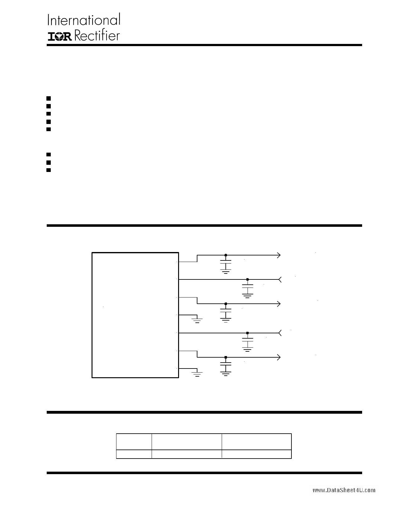
TYPICAL APPLICATION
www.DataSheet4U.com
V26
VDD
IRU1237SC V8
Gnd8
VCC
V33
Gnd26/33
10uF
1uF
1uF
2.6V / 1.2A
12V
8V / 200mA
10uF
10uF
5V
3.3V / 1.2A
Figure 1 - Typical application of IRU1237SC.
PACKAGE ORDER INFORMATION
TJ (°C)
0 To 150
7-PIN PLASTIC
Ultra Thin-PakTM (P)
IRU1237SCCP
PACKAGE
MARKING
US1237SCCP
Rev. 1.2
07/14/03
www.irf.com
1
1 page 
IRU1237SC
APPLICATION INFORMATION
Introduction
The IRU1237SC regulator is 7-pin terminal device and
contains three integrated, fixed, linear regulators. The
dual inputs provide a low dropout voltage for V33 and V26
by biasing the base current to power NPN transistors.
The IRU1237SC is designed to meet the fast current
transient needs as well as an accurate initial voltage,
thus reducing the overall system cost with the need for
fewer number of output capacitors.
Thermal Design
The IRU1237SC incorporates an internal thermal shut-
down that protects the device when the junction tem-
perature exceeds the allowable maximum junction tem-
perature. Although this device can operate with junction
temperatures in the range of 1508C, it is recommended
that the selected heat sink be chosen such that during
maximum continuous load operation the junction tem-
perature is kept below this number.
Thermal Protection
The IRU1237SC provides thermal protection for all three
outputs. All outputs will be disabled for any over-tem-
perature condition. When one of the outputs exceeds
the thermal limit (typically 1508C), the IRU1237SC shuts
down all three outputs simultaneously. The outputs will
be re-enabled when the temperature drops below the
thermal limit.
Current Limit Protection
The IRU1237SC provides over current protection when
one the outputs’ current exceeds the current limit level.
The following thermal design illustrates the method used
to calculate the maximum junction temperature of the
regulator.
VIN1=5.25V
VIN2=12V
VOUT1=2.6V
VOUT2=3.3V
VOUT3=8V
IOUT1=0.5A
IOUT2=0.5A
IOUT3=0.1A
Calculating the maximum power dissipation:
PD = ( VIN1-VOUT1)3 IOUT1+(VIN1-VOUT2) 3 IOUT2+(VIN2-
VOUT3)3 IOUT3
PD = (5.25-2.6)30.5+(5.25-3.3)30.5+(12-8)30.1
PD = 2.7W
Stability
For Ultra Thin-PakTM we have:
The IRU1237SC doesn’t require input and output capaci-www.DataSheet4U.com RTH(JA)=30W/8C
tors for stability, however to improve the transient re-
TA = 508C
sponse and guarantee stability, it is recommended that
DT = PD3RTH(JA) = 2.7W330 = 818C
a 0.1mF (minimum) ceramic for input and output capaci-
TJ = TA+DT = 1318C
tors be used.
Layout Consideration
Transient Response and PSRR
The IRU1237SC, like many other high-speed regulators,
The input and output capacitors are critical in order to requires that the output capacitors be close to the de-
ensure good transient response and PSSR. The most vice for stability. For power consideration, a ground plane
important aspects of this are capacitor selection, place- pad of approximately one-inch square on the compo-
ment, and trace routing. Place each capacitor as close nent side must be dedicated to device where all ground
as physically possible to it’s corresponding regulator pin. pins are connected to dissipate the power. The copper
Use wide traces for low inductance path. Couple directly area under the package shall have vias to the internal
to the ground and power planes as possible. The use of ground plane. The thermal ground plane shall extend out
low ESR capacitors is crucial to achieving good results. from the regulator to open areas of the PCB. All open
An input capacitance of at least 0.1mF is recommended. areas shall be filled with copper to help radiate heat from
An output capacitance of at least 0.1mF with low ESR is the PCB.
recommended for good PSSR at high frequencies. Ce-
ramic capacitors are a good choice for low ESR. Larger
capacitance and lower ESR will improve both PSSR and
transient response.
Rev. 1.2
07/14/03
www.irf.com
5
5 Page | ||
| Páginas | Total 7 Páginas | |
| PDF Descargar | [ Datasheet 1237SC.PDF ] | |
Hoja de datos destacado
| Número de pieza | Descripción | Fabricantes |
| 1237SC | IRU1237SC | International Rectifier |
| Número de pieza | Descripción | Fabricantes |
| SLA6805M | High Voltage 3 phase Motor Driver IC. |
Sanken |
| SDC1742 | 12- and 14-Bit Hybrid Synchro / Resolver-to-Digital Converters. |
Analog Devices |
|
DataSheet.es es una pagina web que funciona como un repositorio de manuales o hoja de datos de muchos de los productos más populares, |
| DataSheet.es | 2020 | Privacy Policy | Contacto | Buscar |