|
|
|
PDF MC34119 Data sheet ( Hoja de datos )
| Número de pieza | MC34119 | |
| Descripción | LOW POWER AUDIO AMPLIFIER | |
| Fabricantes | Motorola Semiconductors | |
| Logotipo | ||
Hay una vista previa y un enlace de descarga de MC34119 (archivo pdf) en la parte inferior de esta página. Total 12 Páginas | ||
|
No Preview Available !
Order this document by MC34119/D
Low Power Audio Amplifier
The MC34119 is a low power audio amplifier intergrated circuit intended
(primarily) for telephone applications, such as in speakerphones. It provides
differential speaker outputs to maximize output swing at low supply voltages
(2.0 V minimum). Coupling capacitors to the speaker are not required. Open
loop gain is 80 dB, and the closed loop gain is set with two external resistors.
A Chip Disable pin permits powering down and/or muting the input signal.
The MC34119 is available in standard 8–pin DIP, SOIC package, and
TSSOP package.
• Wide Operating Supply Voltage Range (2.0 V to 16 V), Allows
Telephone
Line Powered Applications
• Low Quiescent Supply Current (2.7 mA Typ) for Battery
Powered Applications
• Chip Disable Input to Power Down the IC
• Low Power–Down Quiescent Current (65 µA Typ)
• Drives a Wide Range of Speaker Loads (8.0 Ω and Up)
• Output Power Exceeds 250 mW with 32 Ω Speaker
• Low Total Harmonic Distortion (0.5% Typ)
• Gain Adjustable from <0 dB to >46 dB for Voice Band
• Requires Few External Components
MAXIMUM RATINGS
Rating
Supply Voltage
Maximum Output Current at VO1, VO2
Maximum Voltage @ Vin, FC1, FC2, CD
Applied Output Voltage to VO1, VO2 when disabled
Junction Temperature
NOTE: ESD data available upon request.
Value
–1.0 to +18
±250
–1.0, VCC + 1.0
–1.0, VCC + 1.0
–55, +140
Unit
Vdc
mA
Vdc
°C
MC34119
LOW POWER
AUDIO AMPLIFIER
SEMICONDUCTOR
TECHNICAL DATA
8
1
P SUFFIX
PLASTIC PACKAGE
CASE 626
8
1
D SUFFIX
PLASTIC PACKAGE
CASE 751
(SO–8)
8
1
DTB SUFFIX
PLASTIC PACKAGE
CASE 948J
(TSSOP)
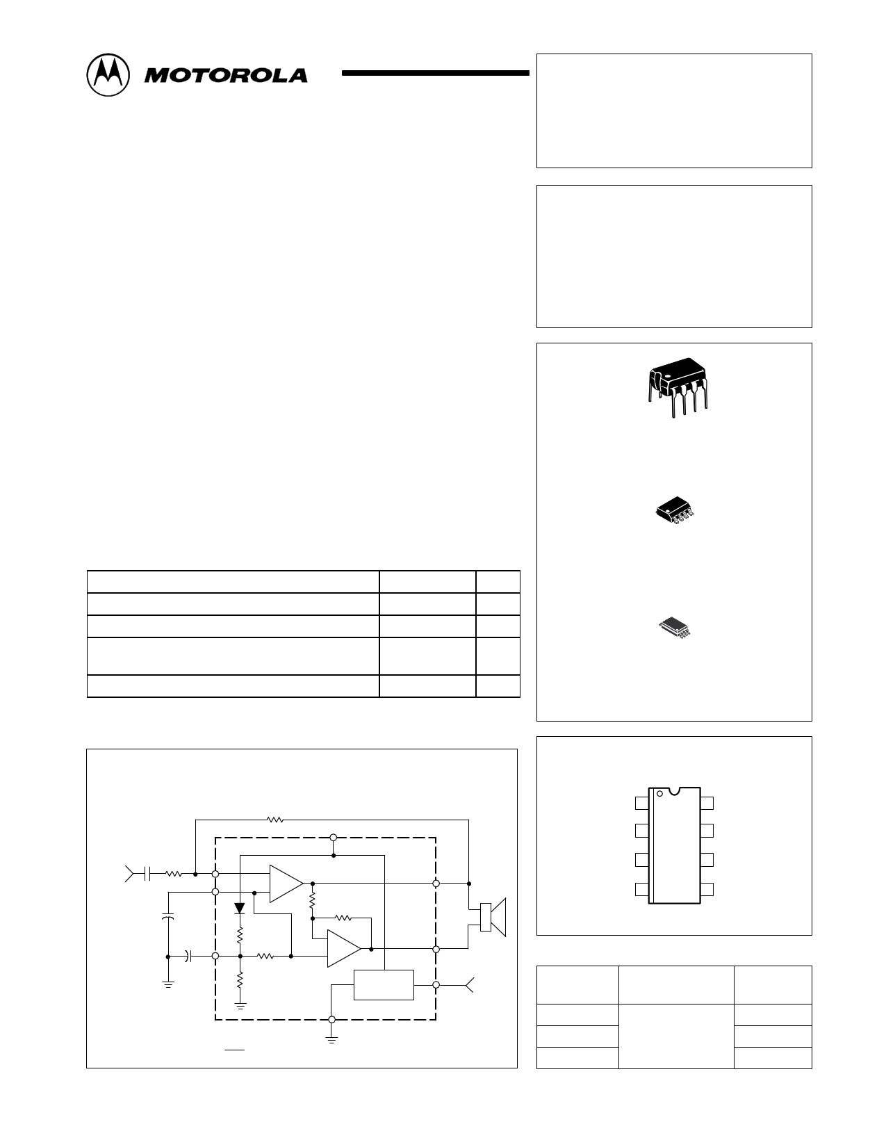
Block Diagram and Simplified Application
Rf
75 k
6 VCC
Audio
Input
Ci
0.1
Ri
3.0 k
Vin
FC1
C1
1.0 µF
C2*
5.0 µF
FC2
* = Optional
Differential Gian = 2 x
4
–
3 + #1
4.0 k
4.0 k
5 VO1
Speaker
50 k
2 125 k
–
#2
+
8 VO2
50 k Bias 1 CD Chip
Circuit
Disable
MC34119
7
Gnd
Rf
Ri This device contains 45 active transistors.
MOTOROLA ANALOG IC DEVICE DATA
PIN CONNECTIONS
CD 1
FC2 2
8 VO2
7 Gnd
FC1 3
6 VCC
Vin 4
5 VO1
(Top View)
ORDERING INFORMATION
Device
Operating
Temperature Range Package
MC34119P
MC34119D TA = –20° to +70°C
MC34119DTB
Plastic DIP
SO–8
TSSOP
© Motorola, Inc. 1996
Rev 1
1
1 page 
MC34119
of each of the three curves is defined by the power level at
which 10% distortion occurs. The center flat portion of each
curve is defined by the maximum output current capability of
the MC34119. The right (descending) portion of each curve is
defined by the maximum internal power dissipation of the IC
at 25°C. At higher ambient temperatures, the maximum load
power must be reduced according to the above equations.
Operating the device beyond the current and junction
temperature limits will degrade long term reliability.
Layout Considerations
Normally a snubber is not needed at the output of the
MC34119, unlike many other audio amplifiers. However, the
PC board layout, stray capacitances, and the manner in
which the speaker wires are configured, may dictate
otherwise. Generally, the speaker wires should be twisted
tightly, and not more than a few inches in length.
Figure 2. Amplifier #1 Open Loop Gain and Phase
100 0
36
80
Phase
72
108
60 144
Gain
40
180
20
0
100 1.0 k
10 k
100 k
1.0 M
f, FREQUENCY (Hz)
Figure 3. Differential Gain versus Frequency
36
Rf = 150 k, Ri = 6.0 k
32
24
16
8
0
100
Rf = 75 k, Ri = 3.0 k
Rf
0.1
Input
Ri –+#1
VO1
VO2 VO
#2
1.0 k 10 k 20 k
f, FREQUENCY (Hz)
MOTOROLA ANALOG IC DEVICE DATA
5
5 Page 
MC34119
OUTLINE DIMENSIONS
DTB SUFFIX
PLASTIC PACKAGE
CASE 948J–01
(TSSOP)
ISSUE O
0.15 (0.006) T U S
2X L/2
L
PIN 1
IDENT.
0.15 (0.006) T U S
0.10 (0.004)
–T– SEATING
PLANE
D
C
8x K REF
0.10 (0.004) M T U S V S
85
B
–U–
J J1ÇÇÇÉÉÇÇÇKKÉÉÇÇÇ1
SECTION N–N
14
A
–V–
N
0.25 (0.010)
M
N
F
DETAIL E
–W–
G SEE DETAIL E
H
NOTES:
1 DIMENSIONING AND TOLERANCING PER ANSI
Y14.5M, 1982.
2 CONTROLLING DIMENSION: MILLIMETER.
3 DIMENSION A DOES NOT INCLUDE MOLD FLASH.
PROTRUSIONS OR GATE BURRS. MOLD FLASH
OR GATE BURRS SHALL NOT EXCEED 0.15
(0.006) PER SIDE.
4 DIMENSION B DOES NOT INCLUDE INTERLEAD
FLASH OR PROTRUSION. INTERLEAD FLASH OR
PROTRUSION SHALL NOT EXCEED 0.25 (0.010)
PER SIDE.
5 DIMENSION K DOES NOT INCLUDE DAMBAR
PROTRUSION. ALLOWABLE DAMBAR
PROTRUSION SHALL BE 0.08 (0.003) TOTAL IN
EXCESS OF THE K DIMENSION AT MAXIMUM
MATERIAL CONDITION.
6 TERMINAL NUMBERS ARE SHOWN FOR
REFERENCE ONLY.
7 DIMENSION A AND B ARE TO BE DETERMINED
AT DATUM PLANE –W–.
MILLIMETERS
INCHES
DIM MIN MAX MIN MAX
A 2.90 3.10 0.114 0.122
B 4.30 4.50 0.169 0.177
C ––– 1.20 ––– 0.047
D 0.05 0.15 0.002 0.006
F 0.50 0.75 0.020 0.030
G 0.65 BSC
0.026 BSC
H 0.50 0.60 0.020 0.024
J 0.09 0.20 0.004 0.008
J1 0.09 0.16 0.004 0.006
K 0.19 0.30 0.007 0.012
K1 0.19 0.25 0.007 0.010
L 6.40 BSC
0.252 BSC
M 0_ 8_ 0_ 8_
MOTOROLA ANALOG IC DEVICE DATA
11
11 Page | ||
| Páginas | Total 12 Páginas | |
| PDF Descargar | [ Datasheet MC34119.PDF ] | |
Hoja de datos destacado
| Número de pieza | Descripción | Fabricantes |
| MC3411 | P-Channel 20-V (D-S) MOSFET | Freescale |
| MC34114 | TELEPHONE SPEECH NETWORK WITH DIALER INTERFACE | Motorola Semiconductors |
| MC34115 | CONTINUOUSLY VARIABLE SLOPE DELTA MODULATOR/DEMODULATOR | Motorola Semiconductors |
| MC34117 | Telephone Tone Riger | Motorola Semiconductors |
| Número de pieza | Descripción | Fabricantes |
| SLA6805M | High Voltage 3 phase Motor Driver IC. |
Sanken |
| SDC1742 | 12- and 14-Bit Hybrid Synchro / Resolver-to-Digital Converters. |
Analog Devices |
|
DataSheet.es es una pagina web que funciona como un repositorio de manuales o hoja de datos de muchos de los productos más populares, |
| DataSheet.es | 2020 | Privacy Policy | Contacto | Buscar |