|
|
|
PDF A3973SLB Data sheet ( Hoja de datos )
| Número de pieza | A3973SLB | |
| Descripción | DUAL DMOS FULL-BRIDGE MICROSTEPPING PWM MOTOR DRIVER | |
| Fabricantes | Allegro MicroSystems | |
| Logotipo | ||
Hay una vista previa y un enlace de descarga de A3973SLB (archivo pdf) en la parte inferior de esta página. Total 12 Páginas | ||
|
No Preview Available !
3973
PRELIMINARY INFORMATION DUAL DMOS FULL-BRIDGE MICRO-
(Subject to change without notice)
December 1, 2000
STEPPING PWM MOTOR DRIVER
VCP 1
CP1 2
CP2 3
OUT1B 4
LOAD
SUPPLY1 5 VBB1
GROUND 6
GROUND 7
SENSE1 8
OUT1A 99
STROBE 10
CLOCK 11
DATA 12
24 OSC
23 SLEEP
22 VREG
21 OUT2B
20 LOAD
VBB2
SUPPLY2
19 GROUND
18 GROUND
17 SENSE2
16 OUT2A
VDD
15
LOGIC
SUPPLY
14 MUX
13 REF
Dwg. PP-069-3
ABSOLUTE MAXIMUM RATINGS
at TA = +25°C
Load Supply Voltage, VBB ................ 35 V
Output Current, IOUT ...................... ±1.0 A
Logic Supply Voltage, VDD .............. 7.0 V
Logic Input Voltage Range,
VIN ................ -0.3 V to VDD + 0.3 V
Reference Voltage, VREF ..................... 3 V
Sense Voltage (dc), VS ................ 500 mV
Package Power Dissipation, PD
A3973SB ............................... 3.1 W
A3973SLB ............................ 2.2 W
Operating Temperature Range,
TA .......................... -20°C to +85°C
Junction Temperature, TJ ............. +150°C
Storage Temperature Range,
TS ......................... -55°C to +150°C
Output current rating may be limited by duty
cycle, ambient temperature, and heat sinking.
Under any set of conditions, do not exceed the
specified current rating or a junction tempera-
ture of 150°C.
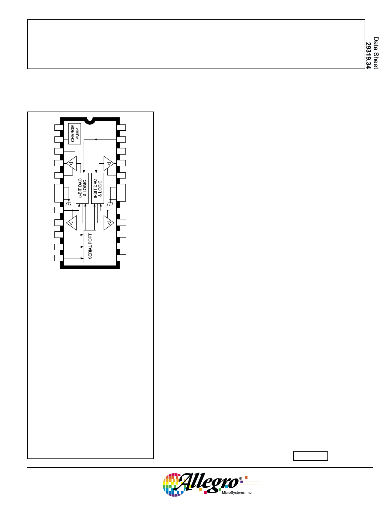
Designed for pulse-width modulated (PWM) current control of
bipolar microstepping stepper motors, the A3973SB and A3973SLB are
capable of continuous output currents to ±1 A and operating voltages to
35 V. Internal fixed off-time PWM current-control timing circuitry can
be programmed via a serial interface to operate in slow, fast, and mixed
current-decay modes. The A3973SB (DIP) and the A3973SLB (SOIC)
are electrically identical and differ only in package style.
The desired load-current level is set via the serial port with two 6-bit
linear DACs in conjunction with a reference voltage. The six bits of
control allow maximum flexibility in torque control for a variety of step
methods, from microstepping to full-step drive. Load current is set in
1.56% increments of the maximum value.
Synchronous rectification circuitry allows the load current to flow
through the low rDS(on) of the DMOS output driver during the current
decay. This feature will eliminate the need for external clamp diodes in
most applications, saving cost and external component count, while
minimizing power dissipation.
Internal circuit protection includes thermal shutdown with hyster-
esis, transient-suppression diodes, and crossover-current protection.
Special power-up sequencing is not required.
The A3973SB is supplied in a 24-lead plastic DIP with a copper
batwing power tab; the A3973SLB is supplied in a 24-lead plastic SOIC
with a copper batwing power tab for surface-mount applications. The
power tabs are at ground potential and need no electrical isolation.
FEATURES
I ±1 A, 35 V Continuous Output Rating
I Low rDS(on) DMOS Output Drivers
I Optimized Microstepping via 6-Bit Linear DACs
I Programmable Mixed, Fast, and Slow Current-Decay Modes
I 4 MHz Internal Oscillator for Digital Timing
I Serial-Interface Controls Chip Functions
I Synchronous Rectification for Low Power Dissipation
I Internal UVLO and Thermal Shutdown Circuitry
I Crossover-Current Protection
I Precision 2 V Reference
I Inputs Compatible with 3.3 V or 5 V Control Signals
I Sleep and Idle Modes
Always order by complete part number, e.g., A3973SB .
1 page 
3973
DUAL DMOS FULL-BRIDGE
MICROSTEPPING PWM MOTOR DRIVER
FUNCTIONAL DESCRIPTION
Serial Interface. The A3973SB/SLB is controlled via a
3-wire (clock, data, strobe) serial port. The programmable
functions allow maximum flexibility in configuring the PWM to
the motor drive requirements. The serial data is written as two
19-bit words: 1 bit to select the word and 18 bits of data. The
serial data is clocked in starting with D18.
Word 0 Bit Assignments
Bit Function
D0 Word select = 0
D1 Bridge 1, DAC, LSB
D2 Bridge 1, DAC, bit 2
D3 Bridge 1, DAC, bit 3
D4 Bridge 1, DAC, bit 4
D5 Bridge 1, DAC, bit 5
D6 Bridge 1, DAC, MSB
D7 Bridge 2, DAC, LSB
D8 Bridge 2, DAC, bit 2
D9 Bridge 2, DAC, bit 3
D10 Bridge 2, DAC, bit 4
D11 Bridge 2, DAC, bit 5
D12 Bridge 2, DAC, MSB
D13 Bridge 1 phase
D14 Bridge 2 phase
D15 Bridge 1 mode
D16 Bridge 2 mode
D17 REF select
D18 Range select
D1 – D6 Bridge 1 Linear DAC. Six-bit word sets desired
current level for Bridge 1. Setting all six bits to zero disables
Bridge 1, with all drivers off (See current regulation section of
functional description).
D7 – D12 Bridge 2 Linear DAC. Six-bit word sets desired
current level for Bridge 2. Setting all six bits to zero disables
Bridge 2, with all drivers off (See current regulation section of
functional description).
D13 Bridge 1 Phase. This bit controls the direction of
output current for Load 1.
D13
OUT1A
OUT1B
0 LH
1HL
D14 Bridge 2 Phase. This bit controls the direction of
output current for Load 2.
D14
OUT2A
OUT2B
0 LH
1HL
D15 Bridge 1 Mode.
D15
Mode
0 Mixed-decay
1 Slow-decay
D16 Bridge 2 Mode.
D16
Mode
0 Mixed-decay
1 Slow-decay
D17 REF Select. This bit determines the reference input for
the 6-bit linear DACs.
D17 Reference Voltage
0 Internal 2 V
1 External (3 V max)
D18 Gm Range Select. This bit determines the scaling factor
(4 or 8) used.
D18 Divider
Load Current
0 1/8
1 1/4
ITRIP = VDAC/8RS
ITRIP = VDAC/4RS
www.allegromicro.com
continued next page ...
5
5 Page 
3973
DUAL DMOS FULL-BRIDGE
MICROSTEPPING PWM MOTOR DRIVER
www.allegromicro.com
The products described here are manufactured under one or more
U.S. patents or U.S. patents pending.
Allegro MicroSystems, Inc. reserves the right to make, from time to
time, such departures from the detail specifications as may be
required to permit improvements in the performance, reliability, or
manufacturability of its products. Before placing an order, the user is
cautioned to verify that the information being relied upon is current.
Allegro products are not authorized for use as critical components
in life-support devices or systems without express written approval.
The information included herein is believed to be accurate and
reliable. However, Allegro MicroSystems, Inc. assumes no responsi-
bility for its use; nor for any infringement of patents or other rights of
third parties which may result from its use.
11
11 Page | ||
| Páginas | Total 12 Páginas | |
| PDF Descargar | [ Datasheet A3973SLB.PDF ] | |
Hoja de datos destacado
| Número de pieza | Descripción | Fabricantes |
| A3973SLB | DUAL DMOS FULL-BRIDGE MICROSTEPPING PWM MOTOR DRIVER | Allegro MicroSystems |
| Número de pieza | Descripción | Fabricantes |
| SLA6805M | High Voltage 3 phase Motor Driver IC. |
Sanken |
| SDC1742 | 12- and 14-Bit Hybrid Synchro / Resolver-to-Digital Converters. |
Analog Devices |
|
DataSheet.es es una pagina web que funciona como un repositorio de manuales o hoja de datos de muchos de los productos más populares, |
| DataSheet.es | 2020 | Privacy Policy | Contacto | Buscar |