|
|
|
PDF J201 Data sheet ( Hoja de datos )
| Número de pieza | J201 | |
| Descripción | N-Channel JFETs | |
| Fabricantes | Vishay | |
| Logotipo | ||
Hay una vista previa y un enlace de descarga de J201 (archivo pdf) en la parte inferior de esta página. Total 6 Páginas | ||
|
No Preview Available !
N-Channel JFETs
J/SST201 Series
Vishay Siliconix
PRODUCT SUMMARY
Part Number
J/SST201
J/SST202
J/SST204
VGS(off) (V)
−0.3 to −1.5
−0.8 to −4
−0.3 to −2
V(BR)GSS Min (V)
−40
−40
−25
gfs Min (mS)
0.5
1
0.5
IDSS Min (mA)
0.2
0.9
0.2
J201
J202
J204
SST201
SST202
SST204
FEATURES
D Low Cutoff Voltage: J201 <1.5 V
D High Input Impedance
D Very Low Noise
D High Gain: AV = 80 @ 20 mA
BENEFITS
D Full Performance from Low Voltage
Power Supply: Down to 1.5 V
D Low Signal Loss/System Error
D High System Sensitivity
D High Quality Low-Level Signal
Amplification
APPLICATIONS
D High-Gain, Low-Noise Amplifiers
D Low-Current, Low-Voltage
Battery-Powered Amplifiers
D Infrared Detector Amplifiers
D Ultra High Input Impedance
Pre-Amplifiers
DESCRIPTION
The J/SST201 series features low leakage, very low noise,
and low cutoff voltage for use with low-level power supplies.
The J/SST201 is excellent for battery powered equipment and
low current amplifiers.
The J series, TO-226 (TO-92) plastic package, provides low
cost, while the SST series, TO-236 (SOT-23) package,
provides surface-mount capability. Both the J and SST series
are available in tape-and-reel for automated assembly (see
Packaging Information).
For similar products in TO-206AA (TO-18) packaging, see the
2N4338/4339/4340/4341 data sheet.
For applications information see AN102 and AN106.
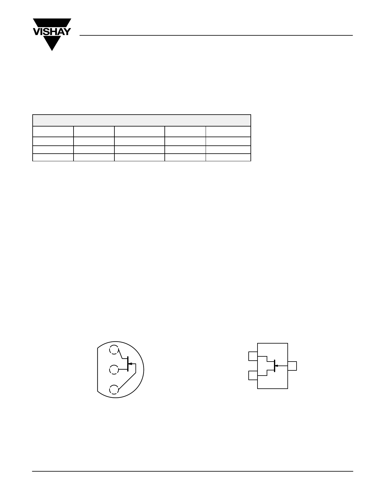
TO-226AA
(TO-92)
D1
S2
G3
Top View
J201
J202
J204
TO-236
(SOT-23)
D1
S2
3G
Top View
SST201 (P1)*
SST202 (P2)*
SST204 (P4)*
*Marking Code for TO-236
Document Number: 70233
S-40393—Rev. G, 15-Mar-04
www.vishay.com
1
1 page 
J/SST201 Series
Vishay Siliconix
TYPICAL CHARACTERISTICS (TA = 25_C UNLESS OTHERWISE NOTED)
Common-Source Input Capacitance
vs. Gate-Source Voltage
10
Common-Source Reverse Feedback Capacitance
vs. Gate-Source Voltage
5
f = 1 MHz
f = 1 MHz
84
6
VDS = 0 V
4
10 V
2
0
0 −4 −8 −12 −16 −20
VGS − Gate-Source Voltage (V)
Output Conductance vs. Drain Current
3
VGS(off) = −1.5 V
2.4
VDS = 10 V
f = 1 kHz
1.8
TA = −55_C
0.8
25_C
0.4
125_C
0
0.01
0.1
ID − Drain Current (mA)
1
Output Characteristics
300
VGS(off) = −0.7 V
240
VGS = 0 V
−0.1
180
−0.2
120
−0.5
−0.3
60 −0.4
0
0 0.1 0.2 0.3 0.4 0.5
VDS − Drain-Source Voltage (V)
Document Number: 70233
S-40393—Rev. G, 15-Mar-04
3
VDS = 0 V
2
1 10 V
0
0 −4 −8 −12 −16 −20
VGS − Gate-Source Voltage (V)
Equivalent Input Noise Voltage vs. Frequency
20
VDS = 10 V
16
12 ID @ 100 mA
8
VGS = 0 V
4
0
10
100 1 k 10 k
f − Frequency (Hz)
Output Characteristics
1.0
VGS(off) = −1.5 V
0.8 VGS = 0 V
0.6 −0.3
100 k
0.4
0.2
0
0
−0.6
−0.9
−1.2
0.2 0.4 0.6 0.8
VDS − Drain-Source Voltage (V)
1.0
www.vishay.com
5
5 Page | ||
| Páginas | Total 6 Páginas | |
| PDF Descargar | [ Datasheet J201.PDF ] | |
Hoja de datos destacado
| Número de pieza | Descripción | Fabricantes |
| J201 | N-Channel JFETs | Vishay |
| J201 | N-Channel General Purpose Amplifier | Fairchild Semiconductor |
| J201 | N-Channel JFET General Purpose Amplifier | Calogic LLC |
| J201 | HIGH GAIN N-CHANNEL JFET | Linear Integrated Systems |
| Número de pieza | Descripción | Fabricantes |
| SLA6805M | High Voltage 3 phase Motor Driver IC. |
Sanken |
| SDC1742 | 12- and 14-Bit Hybrid Synchro / Resolver-to-Digital Converters. |
Analog Devices |
|
DataSheet.es es una pagina web que funciona como un repositorio de manuales o hoja de datos de muchos de los productos más populares, |
| DataSheet.es | 2020 | Privacy Policy | Contacto | Buscar |