|
|
|
PDF SP7652 Data sheet ( Hoja de datos )
| Número de pieza | SP7652 | |
| Descripción | 6A 28V 600KHz Synchronous Step Down Regulator | |
| Fabricantes | Exar | |
| Logotipo | ||
Hay una vista previa y un enlace de descarga de SP7652 (archivo pdf) en la parte inferior de esta página. Total 15 Páginas | ||
|
No Preview Available !
July 2012
SP7652
PowerbloxTM
6A 28V 600KHz Synchronous Step Down Regulator
Rev. 2.0.0
GENERAL DESCRIPTION
The SP7652 is a synchronous voltage mode
PWM step down (buck) regulator capable of a
constant output current up to 6Amps. A wide
2.5V to 28V power input voltage range, with
the required 5V biasing voltage, allows
conversions from industry standard 5V, 12V,
18V and 24V power rails.
With a 600kHz constant operating frequency
and integrated high and low side switch, the
SP7652 reduces the overall component count
and solution footprint. In addition to a 1%
output setpoint accuracy, this device provides
high efficiency, low ripple and excellent line
and load regulation. An enable function and
soft start feature allow for controlled power up
sequencing implementation.
Built-in Under voltage lockout (VLO) on both
VCC and VIN, outputs short-circuit and over
temperature protection insure safe operation
under abnormal operating conditions.
The SP7652 is offered in a RoHS compliant,
lead free 26-pin 7mmx4mm DFN package.
APPLICATIONS
Distributed Power Architectures
Point of Load Converters
Power Supply Modules
FPGAs, DSPs and Processors Supplies
FEATURES
6A Continuous Current
2.5V-28V Power Input Voltage Rail
5V Biasing voltage
0.8V Min. Output Voltage – 1% Accuracy
PWM Voltage Mode Control
600kHz Fixed Synchronous Operations
Low RDSON Power Switches
Greater than 92% Efficiency
Type II & III Compensations Support
Programmable Soft Start
UVLO on both VIN and VCC
Pre-biased Output Start-Up
Over Temperature & Short Circuit
Protection/Auto-Restart
RoHS Compliant Lead Free 26-Pin DFN
US Patent #6,922,041
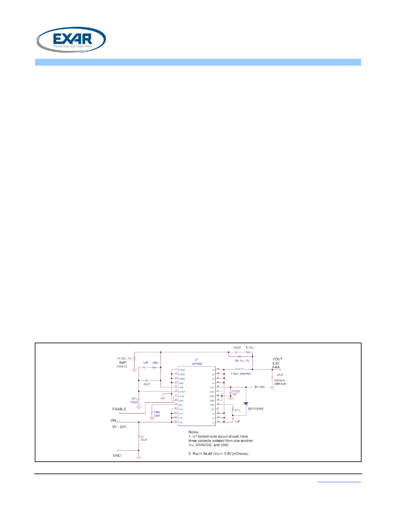
TYPICAL APPLICATION DIAGRAM
Fig. 1: SP7652 Application Diagram
Exar Corporation
48720 Kato Road, Fremont CA 94538, USA
www.exar.com
Tel. +1 510 668-7000 – Fax. +1 510 668-7001
1 page 
SP7652
PowerbloxTM
6A 28V 600KHz Synchronous Step Down Regulator
TYPICAL PERFORMANCE CHARACTERISTICS
All data taken at VIN = 2.7V to 5.5V, TJ = TA = 25°C, unless otherwise specified - Schematic and BOM from Application
Information section of this datasheet.
Fig. 3: Efficiency versus Output Current
VIN=8V, 12V and 15V, VOUT=5V
Fig. 4: Output Voltage versus Output Current
VIN=8V, 12V and 15V
Fig. 5: Efficiency versus Output Current
VIN=5V, VOUT=3.3V
Fig. 6: Output Voltage versus Output Current
VIN=5V, VOUT=3.3V
Fig. 7: Efficiency versus Output Current
VIN=3.3V, VOUT=0.8V
Fig. 8: Output Voltage versus Output Current
VIN=3.3V, VOUT=0.8V
© 2012 Exar Corporation
5/15
Rev. 2.0.0
5 Page 
SP7652
PowerbloxTM
6A 28V 600KHz Synchronous Step Down Regulator
ripple current, the input voltage ripple can be
determined by:
The capacitor type suitable for the output
capacitors can also be used for the input
capacitors. However, exercise additional
caution when tantalum capacitors are used.
Tantalum capacitors are known for
catastrophic failure when exposed to surge
current, and input capacitors are prone to
such surge current when power supplies are
connected “live” to low impedance power
sources.
LOOP COMPENSATION DESIGN
The open loop gain of the whole system can
be divided into the gain of the error amplifier,
PWM modulator, buck converter output stage,
and feedback resistor divider. In order to cross
over at the selected frequency fcoFCO, the
gain of the error amplifier compensates for the
attenuation caused by the rest of the loop at
this frequency.
The goal of loop compensation is to
manipulate loop frequency response such that
its gain crosses over 0db at a slope of -
20db/dec. The first step of compensation
design is to pick the loop crossover frequency.
High crossover frequency is desirable for fast
transient response, but often jeopardizes the
system stability. Crossover frequency should
be higher than the ESR zero but less than 1/5
of the switching frequency. The ESR zero is
contributed by the ESR associated with the
output capacitors and can be determined by:
The next step is to calculate the complex
conjugate poles contributed by the LC output
filter,
When the output capacitors are of a Ceramic
Type, the SP7652 Evaluation Board requires a
Type III compensation circuit to give a phase
boost of 180° in order to counteract the
effects of an underdamped resonance of the
output filter at the double pole frequency
© 2012 Exar Corporation
Fig. 12: SP7652 Voltage Mode Control Loop
11/15
Rev. 2.0.0
11 Page | ||
| Páginas | Total 15 Páginas | |
| PDF Descargar | [ Datasheet SP7652.PDF ] | |
Hoja de datos destacado
| Número de pieza | Descripción | Fabricantes |
| SP7650 | Wide Input Voltage Range 3A / 300kHz / Buck Regulator | Sipex |
| SP7651 | Wide Input Voltage Range 3A / 900kHz / Buck Regulator | Sipex |
| SP7652 | 6A 28V 600KHz Synchronous Step Down Regulator | Exar |
| SP7652 | Wide Input Voltage Range 6A / 600kHz / Buck Regulator | Sipex |
| Número de pieza | Descripción | Fabricantes |
| SLA6805M | High Voltage 3 phase Motor Driver IC. |
Sanken |
| SDC1742 | 12- and 14-Bit Hybrid Synchro / Resolver-to-Digital Converters. |
Analog Devices |
|
DataSheet.es es una pagina web que funciona como un repositorio de manuales o hoja de datos de muchos de los productos más populares, |
| DataSheet.es | 2020 | Privacy Policy | Contacto | Buscar |