|
|
|
PDF XRP7713 Data sheet ( Hoja de datos )
| Número de pieza | XRP7713 | |
| Descripción | Three Channel Digital PWM Step Down Controller | |
| Fabricantes | Exar | |
| Logotipo | ||
Hay una vista previa y un enlace de descarga de XRP7713 (archivo pdf) en la parte inferior de esta página. Total 29 Páginas | ||
|
No Preview Available !
December 2010
XRP7713
Three Channel Digital PWM Step Down Controller
Rev. 1.1.1
GENERAL DESCRIPTION
The XRP7713 is a three output pulse-width
modulated (PWM) step-down DC-DC controller
with a built-in LDO for standby power and
GPIOs. The device provides a complete power
management solution in one IC and is fully
programmable via an I2C serial interface.
Independent Digital Pulse Width Modulator
(DPWM) channels regulate output voltages
and provide all required protection functions
such as current limiting and over-voltage
protection.
Each output voltage can be programmed from
0.9V to 5.1V without the need of an external
voltage divider. The wide range of the
programmable DPWM switching frequency
(from 300 KHz to 1.5 MHz) enables the user to
optimize between efficiency and component
size. Input voltage range is from 4.75V to
25V. An I2C bus interface is provided to
program the IC as well as to communicate
with the host for fault reporting and handling,
power rail parameters monitoring, etc.
The device offers a complete solution including
independently programmable: soft-start, soft-
stop, start-up delay and ramp of each PWM
regulator.
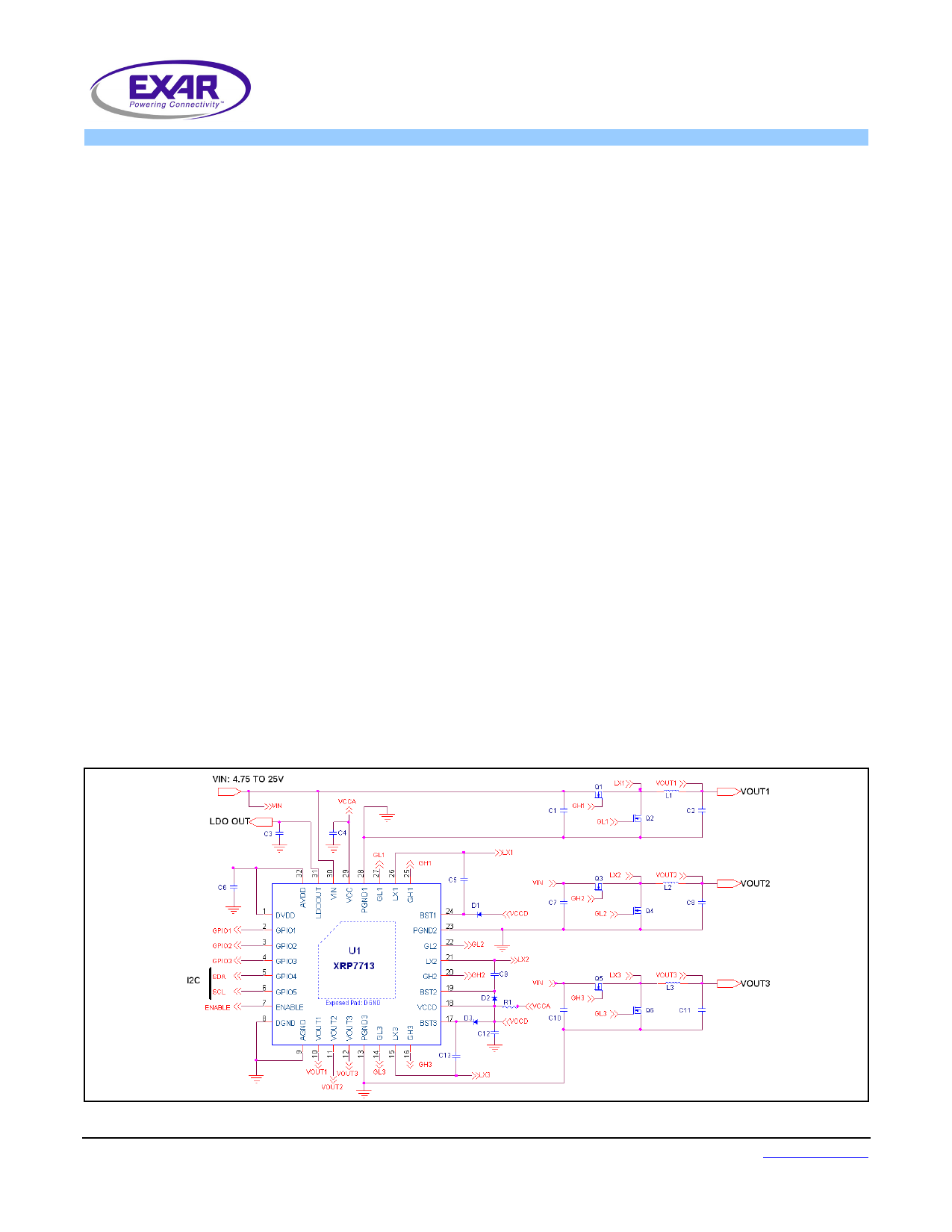
TYPICAL APPLICATION DIAGRAM
APPLICATIONS
• Multi Channel Power Supplies
• Audio-Video Equipments
• Industrial & Telecom Equipments
• Processors & DSPs Based Equipments
FEATURES
• 3 Channel Step Down Controller
− Programmable Output Voltage 0.9V-5.1V
− Programmable 1.5MHz DPWM Frequency
− Integrated FET Drivers
• 4.75V to 5.5V and 5.5V to 25V Input
Voltage Range
• Up to 5 Reconfigurable GPIO Pins
• Fully Programmable via I2C Interface
• Independent Digital Pulse Width
Modulator (DPWM) channels
• Complete Monitoring and Reporting
• Complete Power Up/Down Sequencing
• Full On Board Protection
OTP, UVLO, OCP and OVP
• Built-in 3.3V/5V LDO
• PowerArchitect™ Design Software
• Green/Halogen Free 32-pin TQFN
Fig. 1: XRP7713 Application Diagram
Exar Corporation
48720 Kato Road, Fremont CA 94538, USA
www.exar.com
Tel. +1 510 668-7000 – Fax. +1 510 668-7001
1 page 
BLOCK DIAGRAM
XRP7713
Three Channel Digital PWM Step Down Controller
VOUT1
PreScaler
Vtar
DAC
Feedback
ADC1/2
Channel 1
Digital
PID
Hybrid
DPWM
SS & PD
Isense1
Delay
Gate
Driver
BST1
GH1
LX1
GL1
PGND1
VOUT2
PreScaler
Vtar
DAC
Feedback
ADC1/2
Channel 2
–
Digital
PID
Hybrid
DPWM
SS & PD
Isense2
6
Dead
Time
Gate
Driver
BST2
GH2
LX2
GL2
PGND2
VOUT3
VCC
VDD
GPIO 0-3
SDA,SCL
LDO
GPIO
I2C
VREF
OSC
OTP
Channel 3
Fault
Handling
CLOCK
PWR
Good
Current
ADC1/2
UVLO
Configuration
Registers
VCCD
Isense1
Isense2
Isense3
11-CH
MUX
Vout1
Vout2
Vout3
Vtj
VIN
STBY LR
LDOOUT
© 2010 Exar Corporation
Fig. 2: XRP7713 Block Diagram
5/29
Rev. 1.1.1
5 Page 
XRP7713
Three Channel Digital PWM Step Down Controller
FEATURES AND BENEFITS
General DPWM Benefits:
• Eliminate temperature and time variations associated
with passive components in:
− Output set point
− Feedback compensation
− Frequency set point
− Under voltage lock out
− Input voltage measurement
− Gate drive dead time
• Tighter parameter tolerances including operating
frequency set point
• Easy configuration and re-configuration for different
Vout, Iout, Cout, and Inductor selection by simply
changing internal PID coefficients. No need to change
external passives for a new output specification.
• Higher integration: Many external circuits can be
handled by monitoring or modifying internal registers
• Selectable DPWM frequency and Controller Clock
Frequency
Other Benefits:
• A single voltage is needed for regulation [no External
LDO required].
• I2C interface allows:
− Communication with a System Controller or other
Power Management devices for optimized system
function
− Access to modify or read internal registers that
control or monitor:
− Output Current
− Input and Output Voltage
− Soft-Start/Soft-Stop Time
− ‘Power Good’
− Part Temperature
− Enable/Disable Outputs
− Over Current
− Over Voltage
− Temperature Faults
− Adjusting fault limits and disabling/enabling
faults
− Packet Error Checking (PEC) on I2C communication
• 5 Configurable GPIO pins, (3 if I2C is in use). Pins can
be configured in several ways:
− Fault reporting (including OCP, OVP, Temperature,
Soft-Start in progress, Power Good)
− Allows a Logic Level interface with other non-digital
IC’s or as logic inputs to other devices
− Possible to configure as traditional ‘enable’ pin for
all 3 outputs
− 2 GPIOs can be dedicated to the I2C Interface as
required by the customers design
• Frequency and Synchronization Capability
− Selectable switching frequency between 300kHz and
1.5MHz
− Channel to channel phase relationship is a fixed 90
degrees
− Main oscillator clock and DPWM clock can be
synchronized to external sources
− ‘Master’, ‘Slave’ and ‘Stand-alone’ Configurations
are possible
• Internal MOSFET Drivers
− Internal FET drivers (3Ω/6Ω) for each Channel
− Built-In Automatic Dead-time adjustment
− 30ns Rise and Fall times
• PowerArchitect™ Design and Configuration Software:
− In its simplest form only VIN, VOUT, and Iout for
each channel is required.
− The software calculates configuration register
content based upon customer requirements. PID
coefficients for correct loop response (for automatic
or customized designs) can be generated and sent
to the device.
− Configurations can be saved and/or recalled
− GPIOs can be configured easily and intuitively
− Synchronization configuration can be adjusted
− Interface can be used for real-time debugging and
optimization
• Customizing XRP7713 with customer parameters
− Once a configuration is finalized it can be sent to
EXAR and can reside in pre-programmed parts that
customers can order with an individual part number.
− Allows parts to be used without I2C interface
System Benefits:
• Reliability is enhanced via communication with the
system controller which can obtain real time data on
an output voltage, input voltage and current.
• System processors can communicate with the
XRP7713 directly to obtain data or make adjustments
to react to circuit conditions
• A system process or could also be configured to log
and analyze operating history, perform diagnostics and
if required, take the supply off-line after making other
system adjustments.
• If customer field service is a possibility for your end
product, parameter reporting and history would
provide additional capabilities for troubleshooting or
aid in future system upgrades.
© 2010 Exar Corporation
11/29
Rev. 1.1.1
11 Page | ||
| Páginas | Total 29 Páginas | |
| PDF Descargar | [ Datasheet XRP7713.PDF ] | |
Hoja de datos destacado
| Número de pieza | Descripción | Fabricantes |
| XRP7713 | Three Channel Digital PWM Step Down Controller | Exar |
| XRP7714 | Quad Channel Digital PWM Step Down Controller | Exar |
| Número de pieza | Descripción | Fabricantes |
| SLA6805M | High Voltage 3 phase Motor Driver IC. |
Sanken |
| SDC1742 | 12- and 14-Bit Hybrid Synchro / Resolver-to-Digital Converters. |
Analog Devices |
|
DataSheet.es es una pagina web que funciona como un repositorio de manuales o hoja de datos de muchos de los productos más populares, |
| DataSheet.es | 2020 | Privacy Policy | Contacto | Buscar |